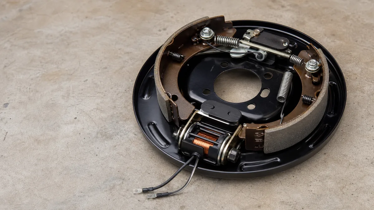
An electric trailer brake circuit carries a controlled output from the tow-vehicle brake controller through the connector to the trailer brake junction. The magnet branches are wired in parallel and return through the trailer and vehicle ground path. This page explains topology, not conductor sizing, protection, controller gain, or axle adjustment.
Identify every component in the brake circuit
The normal path includes the controller’s specified power and signal connections, its brake-output conductor, the vehicle socket and trailer plug, a trailer junction, parallel conductors to each brake magnet, and a complete return path. The breakaway battery and pull switch form a separate emergency source path covered below.
Identify the installed controller and axle/brake manufacturer before testing. Their manuals control connection methods, protection, allowable measurements, adjustment, and diagnostic steps.
Treat the circuit as electrical and mechanical
The diagram contains these electrical boundaries:
| Boundary | What must be established |
|---|---|
| Vehicle power and controller | Correct installation, status, setup, and product-specified protection |
| Controller output to vehicle socket | Output reaches the assigned connector position under the specified test condition |
| Mated connector | Contacts are correctly assigned, retained, clean, and able to carry the operating load |
| Trailer junction and axle branches | Feed divides to every brake branch without an open, short, or high-resistance splice |
| Magnet return path | Every magnet has a complete return to the source |
Electrical output alone does not prove correct braking. Brake adjustment, magnet condition, drum condition, bearings, tires, and axle loading can affect the result. Keep those mechanical checks within the axle manufacturer’s service procedure.
Trace normal controller current to the brake magnets
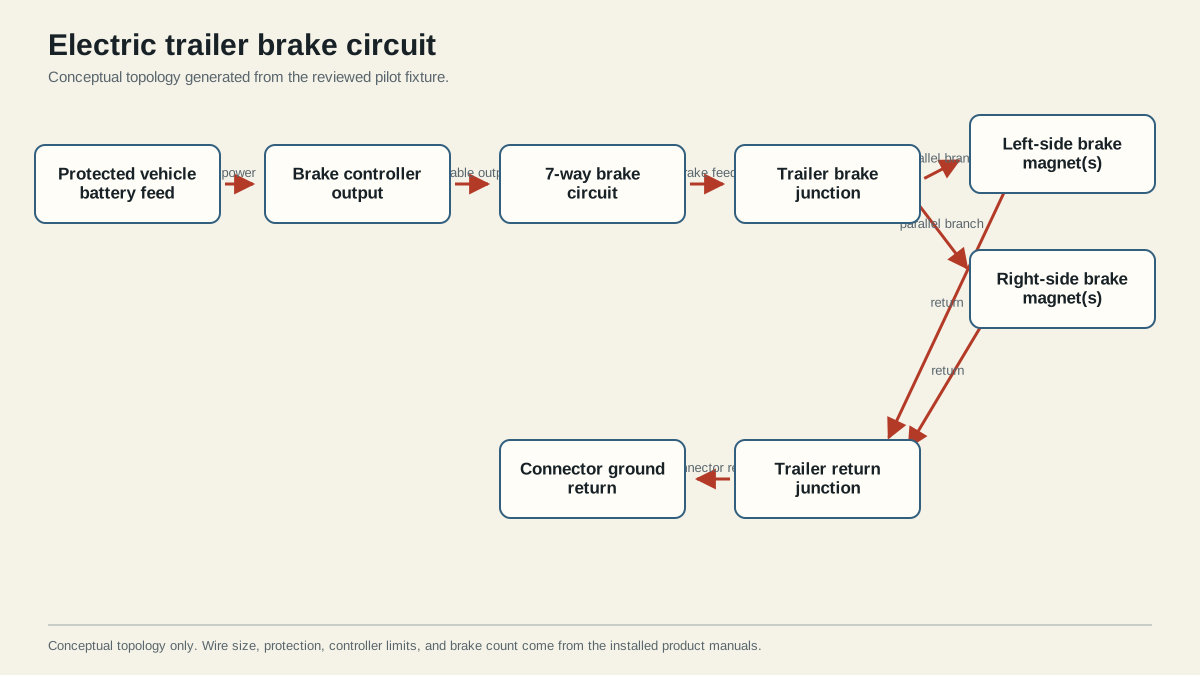
Controller output leaves the tow vehicle on the assigned brake circuit, crosses the connector, and reaches the trailer junction. From there it divides into parallel branches so each brake receives the same commanded source. Dexter’s electric-brake service manual documents parallel brake wiring and the associated service checks.
The ground/return is part of the working circuit. A good brake-output signal with a restricted return can still produce weak or uneven operation.
Why the magnets are parallel branches
Each brake magnet connects across the brake-output and return conductors. The branches are parallel, so the controller’s output is presented to every branch rather than passing through one magnet and then the next. The deterministic diagram uses this topology and the fixture checker rejects a serial chain.
Do not mistake physical routing along an axle for a series electrical connection. A harness may travel from one side to the other while still splicing both magnets across the same feed and return. Confirm the actual junctions instead of judging from cable direction alone.
When one wheel brakes differently from the others, divide the system at the trailer junction and compare branches using the manufacturer’s method. When every brake is weak or absent, first investigate shared boundaries such as controller status, connector output, main brake feed, main return, and mechanical adjustment. These are diagnostic priorities, not proof of a cause.
Separate normal braking from breakaway operation
Normal braking comes from the brake controller and is intended to vary with the driver’s braking command and controller setup. The breakaway path uses the trailer’s specified battery and switch to energize the brake circuit if the trailer separates. It does not route normal braking through the pull switch.
See the breakaway wiring diagram for that emergency path. Follow the controller manual before any breakaway test because some controllers require the trailer plug to be disconnected for that test.
| Operating state | Energy source | Command device | Shared downstream path |
|---|---|---|---|
| Normal service braking | Tow vehicle through the installed controller | Brake controller | Trailer brake junction, parallel magnet branches, and return |
| Breakaway event | Specified onboard breakaway battery | Pull switch | Trailer brake junction, parallel magnet branches, and return |
The two sources meet at the trailer brake circuit but are not interchangeable. The breakaway battery is not the normal controller source, and the controller output should not be routed through the pull switch.
Verify the system against product documentation
Verify connector assignment, controller status, breakaway battery condition, every magnet branch, mechanical brake adjustment, and the complete return path using the installed manuals. Do not infer conductor size, fuse or breaker rating, current expectation, or gain setting from this conceptual drawing.
Isolate a fault without guessing at parts
- Secure the vehicle and trailer and follow the controller and axle safety procedures.
- Record the symptom: no brakes, one weak side, intermittent output, lockup, or controller fault indication.
- Confirm the controller installation and status using its manual.
- Verify the assigned brake output at the vehicle connector using the controller’s specified test method.
- Inspect the connector and verify that output crosses to the trailer main brake conductor.
- Divide at the trailer junction and check each parallel branch and its return.
- Complete the axle manufacturer’s magnet, adjustment, and mechanical checks.
- Reproduce the operating test only after every disturbed connection is secured.
A resistance or continuity result taken with the circuit unpowered is only one piece of evidence. Corrosion or a weak splice may behave differently when current flows. Use the exact voltage, resistance, or current criteria published for the installed magnets and controller rather than applying an uncited universal number.
Stop before towing if braking is absent, uneven, intermittent, overheating, shorted, or inconsistent with controller and axle documentation. A passed visual inspection does not replace the required functional tests.
Sources
Last verified: August 25, 2026.