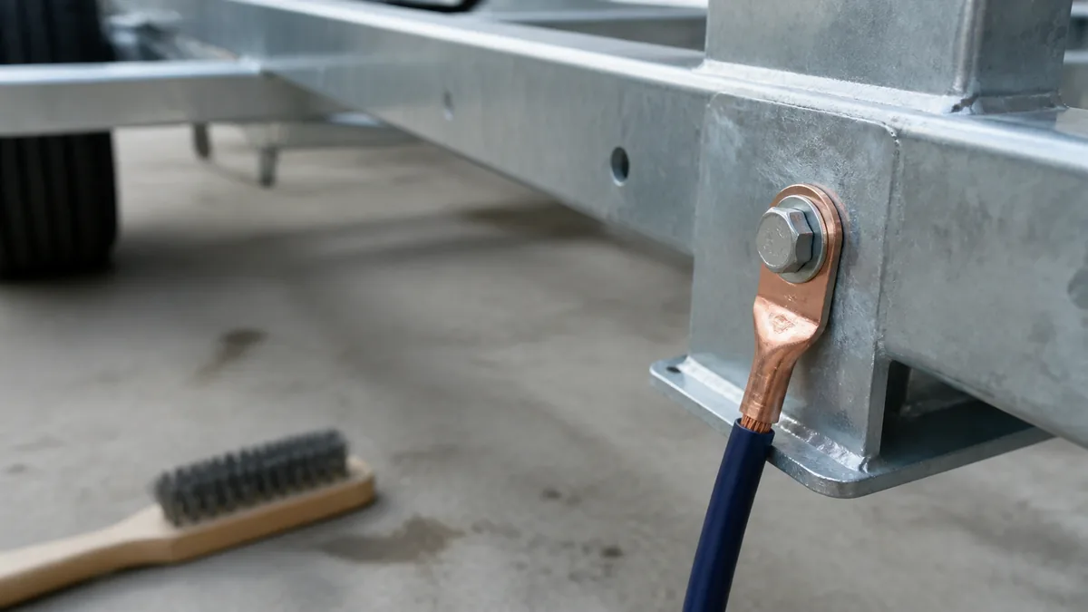
Trailer power and grounding problems become difficult when several circuits share a connector, frame, junction, or battery but do not share the same job. Lighting return, electric-brake return, breakaway operation, auxiliary power, and battery charging can meet at physical boundaries while requiring different protection, tests, and documentation.
Safety limit: This is a system-classification guide, not a wire-size, fuse, battery, charger, or current recommendation. Do not modify a trailer circuit while its source, load, protection, return path, or installed-product limits are unknown. Stop for heat, arcing, damaged insulation, repeated protective-device operation, battery damage, or required braking/lighting faults.
Classify the trailer electrical circuit
Start with the load and source, not the color of a conductor. Record whether the circuit is for lighting, electric brakes, breakaway operation, an auxiliary accessory, a maintenance charge path, or a house-battery charger. Then record when it should operate: with a lamp command, brake command, separated-trailer condition, ignition/engine state, shore power, or a charger control state.
The public scope of SAE J1239 covers connector circuits including lighting, electric brakes, trailer battery charging, auxiliary circuits, color coding, and short/hazard protection. That scope does not prove that the installed vehicle activates every position or that the trailer uses a position for the expected purpose. The 7-way pinout guide is a reference for identification, not permission to energize an unknown contact.
| Circuit class | Source to identify | Load to identify | Evidence that remains necessary |
|---|---|---|---|
| Lighting | Vehicle module, converter, or switch | Lamps and their branches | Function test, return test, and legal/vehicle requirements |
| Electric brakes | Compatible brake controller | Magnet or approved actuator branches | Controller, axle, brake, and loaded return procedures |
| Breakaway | Trailer battery and switch | Brake circuit under emergency operation | Kit, battery, switch, brake technology, and applicable test |
| Auxiliary power | Vehicle auxiliary output or separate supply | Accessory, charger input, or battery system | Product activation state, protection, isolation, and load |
| House-battery charging | Alternator/vehicle supply, DC-DC charger, or shore charger | Battery bank and charger | Charging profile, battery chemistry, isolation, cable path, and limits |
Never let the presence of a 7-way connector turn a maintenance-charge question into a high-demand power design. A contact can be physically available while its vehicle fuse, module, relay, conductor, or charging logic is unsuitable for the proposed load.
Trace source protection conductor load and return
Every circuit needs a complete path: source, protection, outgoing conductor, connection boundaries, load, and return. A frame can be part of a return path, but a frame connection is not automatically a low-resistance or corrosion-free return. A dedicated conductor, frame bond, junction, and connector contact each create a boundary that should be inspectable and testable.
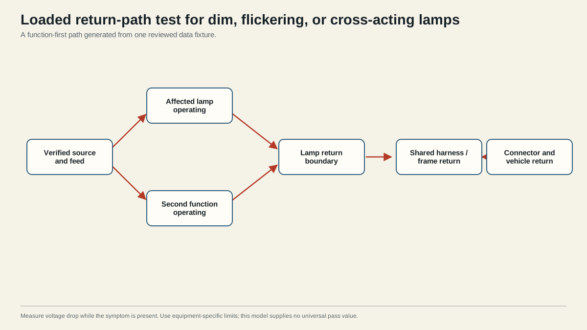
For lighting, test the required function with the load operating. For brakes, follow the controller and axle procedure; a signal at the connector does not prove every magnet branch or mechanical brake is healthy. For breakaway, use the exact kit procedure and do not substitute a normal-service test. For charging, identify whether the vehicle output is switched, current-limited, isolated, or controlled by a module before interpreting a reading.
Inspect each boundary for loose fasteners, paint or coating under a ring terminal, corrosion, unsupported cable, crushed insulation, undersized or overheated terminals, and a connector that cannot retain its contact. Clean metal alone is not evidence of an adequate loaded return. Test the return under the condition that creates the fault and use the equipment manual’s limits.
Separate maintenance charging from high-demand power
A trailer battery may be connected to a tow vehicle through an auxiliary contact, but the word “charging” hides several different systems. A vehicle may provide a switched maintenance feed, a relay-controlled output, a factory trailer module output, or no active feed at all. A battery charger may require a controlled input, an isolation device, a specific charging profile, and its own protection. A battery bank may also be powering an inverter or other high-demand load that the connector was never designed to supply.
Use this decision order:
- Identify the battery chemistry, capacity, state, and charger or converter model.
- Confirm whether the tow vehicle actually activates the auxiliary output in the operating state being tested.
- Identify protection at the source and at the trailer-side energy-storage boundary.
- Trace both positive and return conductors over the complete installed length.
- Confirm the charger input limits, isolation behavior, temperature conditions, and required battery protections.
- Measure the operating path under the load or charge state specified by the product instructions.
Do not infer that a standing reading means a battery is charging, or that a battery’s rising terminal voltage proves an acceptable charge current. Charging performance depends on source behavior, resistance, connections, battery state, charger control, and the equipment limits. If those inputs are unavailable, the correct result is an evidence request or qualified inspection, not a guessed conductor size.
Identify inputs required before sizing or modification
Before changing a power or ground circuit, collect:
- tow vehicle make, model, year, factory or aftermarket tow module, and connector family;
- trailer connector, adapter, cable length, junctions, and actual function assignments;
- load type, steady and startup behavior, duty cycle, and simultaneous loads;
- battery chemistry, bank arrangement, charger/converter model, and manufacturer limits;
- source protection, isolation or relay behavior, and accessible service points;
- outgoing and return conductor material, routing, terminations, environmental exposure, and support;
- brake, breakaway, lighting, and jurisdiction-specific requirements;
- the exact voltage-drop, fuse, temperature, charging, and installation criteria from the responsible manuals or standard.
If a material input is missing, mark the design unverified. Do not copy a gauge or fuse from a different trailer, connector, battery, or charger. A larger conductor can still be incorrectly protected; a frame return can still be intermittent; and a higher-capacity source can still exceed a connector, relay, or module limit.
Use the 7-way auxiliary-power charging procedure to prove source activation, loaded behavior, and charger ownership; the ground troubleshooting guide for an observed return-path symptom; and the electric-brake wiring diagram for brake topology. This hub owns classification and evidence boundaries so those focused pages do not compete for the same intent.