An electric trailer brake system has two jobs that share some hardware but begin from different sources. During normal towing, a brake controller in the tow vehicle commands the trailer brakes. If the trailer separates, a charged breakaway battery and switch must operate the trailer brake circuit independently. Both paths ultimately energize brake components at the wheels, but neither path proves that the other works.
Use this guide as the system map. It explains where each layer begins and ends, what a successful test actually proves, and which focused procedure owns the next task. It does not provide one universal gain, voltage, resistance, wire size, fuse, adjustment, or road-test value. Those limits depend on the installed controller, brake assembly, axle, trailer, vehicle, and breakaway kit.
Safety limit: Do not tow when required trailer braking cannot be confirmed, a controller reports an unresolved fault, wiring is damaged or overheating, a protective device repeatedly opens, or a breakaway system fails its applicable test. Secure the combination against movement before electrical checks. Follow the vehicle, trailer, controller, axle, and breakaway-kit instructions. Brake disassembly, lifting, and road testing require the specified equipment, support points, conditions, and skill.
Identify the normal braking components
Normal service braking begins with the tow vehicle and ends with mechanical friction at the trailer wheels. The complete chain matters because a display value or voltage reading at one point does not prove the next layer.
| Layer | Normal role | Evidence that belongs at this layer | What that evidence does not prove |
|---|---|---|---|
| Tow-vehicle inputs | Provide the controller with the applicable brake and vehicle information | Correct input status under the controller manual | That brake output reaches the trailer |
| Brake controller | Produces a commanded output for compatible trailer brakes | Expected display, connection state, and output behavior for the exact model | That the connector, trailer harness, or brakes can carry and use it |
| Vehicle socket and trailer plug | Transfer brake output and the return path across a removable interface | Correct function at the identified terminal and stable mating contact | That every wire color follows a common chart |
| Trailer junction and harness | Distribute the brake circuit toward the axle or wheel branches | Command remains present under the product-specified test at successive boundaries | That every parallel branch is equal |
| Magnet and actuating hardware | Convert electrical input into motion within an electric drum brake | Exact brake-model checks pass and actuation is observed | That linings, drum surfaces, adjustment, and loading produce adequate braking |
| Brake return path | Completes the circuit to the selected source | Loaded return-path check passes from brake assemblies back to source | That the feed path is also sound |
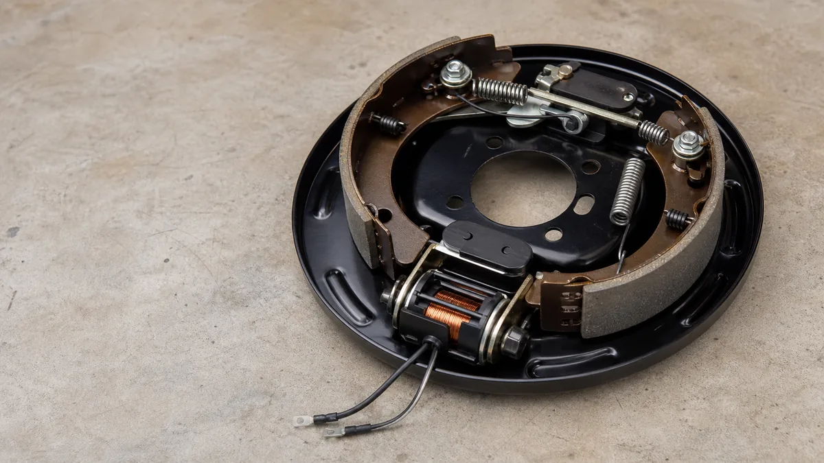
Dexter’s electric-brake service manual describes controller current energizing an electromagnet. The magnet is attracted to the rotating drum armature surface, which moves the actuating lever and applies the shoes to the drum. That sequence explains why electrical actuation and mechanical braking must be evaluated separately. A healthy command cannot compensate for worn, contaminated, damaged, seized, or incorrectly adjusted brake hardware.
Identify the installed system before testing it
Record the facts that control the procedure:
- tow vehicle year, make, model, and factory or aftermarket tow wiring;
- brake controller make, model, compatibility, display state, and current settings;
- connector family, connector half, and viewing orientation;
- trailer identity, axle count, brake type, and exact brake assembly or axle documentation;
- breakaway switch, battery, charger, and kit model;
- recent changes, loading condition, storage history, and the exact symptom;
- whether the symptom occurs with the brake pedal, manual control, breakaway activation, or more than one source.
Do not infer electric drum brakes merely from the presence of a seven-contact connector. A connector supplies circuit capacity, not proof of installed equipment. Some trailers use electric-over-hydraulic actuators, surge systems, or application-specific equipment. A controller may also exclude a brake technology. Identify both ends before applying a procedure.
The controller manual is part of the system. Tekonsha’s electronic brake-control instructions, for example, identify controller inputs, output, manual control, setup, and display-based troubleshooting for covered applications. Another controller can report connection or faults differently. Translate its display using its manual rather than treating a code from another model as universal.
Trace controller output to the brake assemblies
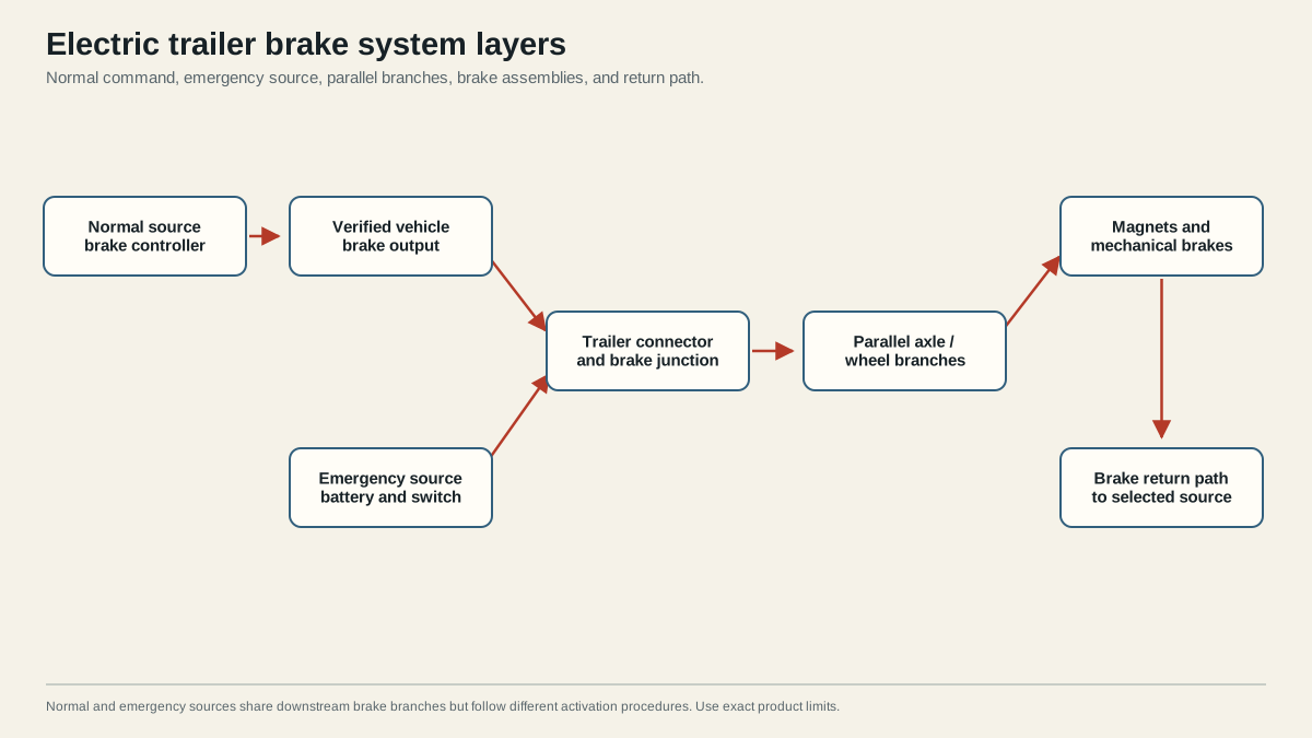
For normal braking, trace the circuit by function: controller output, identified vehicle-socket position, mating trailer-plug position, trailer junction, parallel branches, brake assemblies, and return. The electric trailer brake wiring diagram owns the detailed conceptual topology. This hub focuses on what the layers mean and when to change procedures.
Controller command is not brake force
A proportional controller may vary output with deceleration; other controller types may use different logic. Manual control behavior can also differ from brake-pedal behavior. Read the installed controller instructions before using either control as a diagnostic input. Record the command used, controller setting, display state, vehicle electrical state, trailer connection state, and test point.
If the controller cannot recognize the trailer or cannot produce the expected output according to its own procedure, stay on the vehicle and interface layers. Do not adjust wheel brakes or replace magnets to solve an unverified source. Conversely, a normal display is not a substitute for measuring or observing the downstream system under the specified conditions.
The connector is a boundary, not a color chart
Connector orientation can reverse when a diagram changes between the mating face and wire-entry side. Wire colors can also change after a cord, junction box, vehicle harness, or previous repair. Use the 7-pin trailer wiring guide to identify common function positions, then prove the installed function with appropriate documentation and testing.
A disconnected socket check separates the tow vehicle from the trailer, but it may not reproduce a loaded condition. If an output appears when disconnected and fails only after mating, the fault can still be at the contacts, trailer feed, branches, load, return, or protective vehicle equipment. Preserve the first passing and first failing boundaries instead of concluding that the socket is universally good.
Parallel branches require comparison
Electric brake assemblies are commonly arranged in parallel so each branch receives the brake circuit rather than being placed in a series chain. A main feed can therefore pass while one axle or wheel branch fails. Compare like branches only when the installed brake models and test conditions are known. One different branch is useful evidence; one generic internet value is not.
At the wheel, keep four questions separate:
- Does the required electrical command arrive under the specified test?
- Does the return path remain sound while the circuit is loaded?
- Does the exact magnet or actuator pass its manufacturer check?
- Are adjustment, linings, drum or rotor surfaces, actuating parts, bearings, and related mechanical components serviceable?
Dexter’s troubleshooting material lists electrical causes such as open or short circuits, corroded connections, faulty grounds, controllers, and broken wires alongside mechanical causes such as adjustment, worn or contaminated parts, scored drums, and seized or broken components. This is why increasing gain is not a general repair for weak braking. It can mask evidence while leaving a mechanical or conductor fault unresolved.
Understand the independent breakaway path
A breakaway system is a stored-energy emergency source. In a typical electric-brake arrangement, a battery on the trailer supplies power through a normally inactive breakaway switch when its pin is pulled by a correctly routed cable during separation. Downstream, it can share the trailer brake feed, branches, assemblies, and return used by normal controller operation.
That shared downstream path produces two important diagnostic results:
- If normal braking works but breakaway operation fails, investigate the breakaway battery, charger, switch, cable, wiring, and exact test procedure before blaming every wheel brake.
- If breakaway operation applies the brakes but normal braking fails, the shared downstream circuit may have demonstrated some function, but the controller, vehicle-side wiring, connector interface, command behavior, and normal loaded performance remain unresolved.
Neither result proves complete braking performance. A switch click does not prove battery condition or brake application. A wheel that resists rotation does not prove every wheel responds, that the stored-energy source meets its product requirement, or that normal controller modulation works on the road.
Do not improvise the pull-pin procedure
The correct tow-vehicle connection state, battery preparation, actuation duration, lifting method, observation, reset, and recharge step come from the installed breakaway-kit and brake-system documentation. Some product instructions explicitly require disconnecting the trailer electrical plug before a pull-pin or push-to-test check to protect the controller or system. Do not combine steps from unrelated products.
Use the breakaway-system test guide only after identifying the installed kit. The breakaway switch wiring diagram owns the conceptual source, switch, brake-feed, and return topology. Neither page authorizes a universal duration or connection state.
The breakaway cable is not a parking brake. Its purpose is emergency actuation after separation. Route and attach it exactly as the applicable instructions specify so it can operate without snagging or pulling during normal articulation. Reinsert the pin and restore or recharge the system after an allowed test.
Keep regulatory scope explicit
49 CFR Part 393 contains brake and breakaway requirements for vehicles subject to that federal commercial-motor-vehicle part. It is useful evidence for that covered scope, but it is not a universal rule for every private trailer. State, provincial, local, vehicle-class, weight, use, and inspection requirements can differ. Confirm the rules that apply to the actual combination and journey.
Route setup and fault symptoms to the right procedure
Choose the page that owns the task. Broad system knowledge is useful, but mixing setup, wiring, and fault diagnosis into one procedure can destroy the evidence needed to isolate a failure.
| Actual task or observation | Canonical owner | Why it is separate |
|---|---|---|
| Understand how all layers work together | This guide | Establishes prerequisites and boundaries without prescribing product values |
| Trace controller, connector, parallel branches, and return | Electric trailer brake wiring diagram | Owns conceptual circuit topology |
| Identify the seven-contact brake-output position | 7-pin trailer wiring diagram | Owns connector orientation and function mapping |
| Brakes are absent or weak | Trailer brakes not working | Isolates source, connector, branch, magnet, and mechanical layers |
| Brakes lock, drag, or act unexpectedly | Dedicated locking-brake guide, planned | Requires a different symptom tree from absent braking |
| Set controller gain or synchronization | Dedicated controller setup guide, planned | Values and method depend on controller, brakes, load, and conditions |
| Understand the emergency circuit | Breakaway switch wiring diagram | Owns the independent-source topology |
| Perform a breakaway functional check | How to test a trailer breakaway system | Starts with the exact product procedure and connection state |
Use a boundary record for every repair
A useful service record contains more than the replaced part. Write down:
- system identities and manuals used;
- initial symptom and whether it affected all or selected brakes;
- controller input, display, and command used;
- connector orientation and terminal function;
- measurement type, reference point, load state, and result;
- first passing boundary and first failing boundary;
- exact repair or adjustment performed;
- post-repair normal and breakaway results;
- unresolved variables and the decision to tow or stop.
This record turns a repair into reproducible evidence. It also prevents a later technician from treating a no-load voltage, continuity beep, controller display, or one responsive wheel as proof of the whole system.
Stop conditions take priority over diagnosis speed
Stop towing when adequate braking is not verified or a required breakaway function fails. Also stop for damaged or overheating conductors, repeated fuse or breaker operation, smoke or odor, a loose connector, a battery that is damaged or leaking, inconsistent wheel response, fluid leakage on an applicable hydraulic system, or mechanical damage at a brake or running-gear component.
Use qualified service when the test requires lifting without the specified support equipment, opening a brake assembly without the correct procedure, working around unknown stored energy, resolving vehicle-network or factory tow-module faults, or interpreting a result outside the product manual. Dexter explicitly directs uncertain operators to professional assistance and warns that safe service methods and correct support are essential.
After any repair, verify the system under the controlling instructions. Confirm normal controller operation, every applicable brake branch, connector retention, protected routing, breakaway readiness, and the required road-test or inspection outcome. A passing final result belongs to the complete combination and current load, not to one isolated component.
Sources
- Dexter complete service manual, electric braking section
- Tekonsha electronic brake control instructions
- 49 CFR Part 393
Last verified: August 26, 2026.