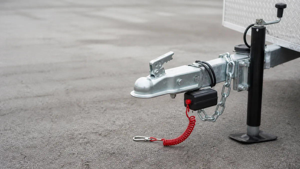
A breakaway system is an emergency source for the trailer’s electric brakes. A specified onboard battery stores energy, a charger maintains that battery as designed, and a normally open pull switch connects battery power to the trailer brake junction when the pin is pulled. Normal controller output remains a separate path described in the electric trailer brake circuit reference.
Identify the breakaway components and their jobs
Identify the installed breakaway battery, its specified charger or battery box, the pull switch and pin, the lanyard, the brake-output junction, magnet branches, and the return path. Confirm the product models and retrieve their instructions before testing or changing wiring.
The lanyard is a mechanical trigger, not a safety chain. Its routing and attachment must follow the installed product and applicable requirements so separation can pull the switch as intended.
Component-by-component check
| Component | Normal role | Failure that the visual alone cannot reveal |
|---|---|---|
| Breakaway battery | Stores energy for emergency brake application | Discharged, aged, wrong type, damaged, or disconnected |
| Charger or battery box electronics | Maintains the battery according to the kit design | Incompatible source, failed charging circuit, or missing protection |
| Pull switch and pin | Closes the emergency feed when separation removes the pin | Corrosion, damage, seized pin, poor contacts, or incorrect wiring |
| Lanyard | Mechanically removes the pin during separation | Routed too loosely, attached to the wrong point, damaged, or entangled |
| Brake junction and magnet branches | Distribute emergency power to every brake | Open branch, weak return, damaged splice, or mechanical brake fault |
The push-to-test indicator found on some battery boxes is product-specific. Determine what its indication actually proves from that kit’s instructions. It may not substitute for the complete operational test required by the manufacturer or applicable rules.
Trace the emergency current path
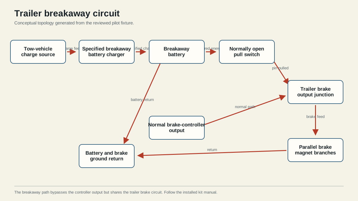
With the pin installed, the pull switch is normally open. When separation pulls the pin, battery power passes through the switch to the trailer brake-output junction, divides among the parallel magnet branches, and returns to the battery through the specified return path. Dexter’s electric-brake service manual documents the battery-powered emergency path.
Follow the path in both directions. From battery positive, trace through the protection and switch arrangement specified by the kit to the brake feed. From every magnet, trace the return back to battery negative. A correct positive-side drawing does not compensate for a missing return.
The normal controller output also joins the brake feed downstream, but normal braking and breakaway activation come from separate sources. Avoid test methods that can backfeed or damage the controller. The installed controller instructions determine whether the vehicle connector must be disconnected before pulling the breakaway pin.
Understand charging without bypassing the specified charger
The tow-vehicle auxiliary feed is not automatically a direct battery-charging instruction. Battery chemistry, charger design, protection, conductor sizing, and connection sequence are product-specific. Route charging only through the components and protection specified by the breakaway kit and vehicle documentation.
Do not bridge the pull switch, substitute an unapproved battery, or use this conceptual drawing to select a fuse. Those decisions require the installed manufacturer’s limits.
Questions the auxiliary-power terminal does not answer
A live 7-way auxiliary terminal does not establish:
- whether it is ignition-switched or continuously powered;
- whether the vehicle requires a fuse, relay, or configuration step;
- whether it is intended to maintain this battery chemistry;
- whether the kit includes its own charger or current-limiting design;
- whether the conductor and protection suit the installed run and load.
Use the kit wiring diagram as a complete system. Some kits incorporate charging electronics in the battery box, while others specify a separate charger. Do not collapse those different designs into a direct wire from vehicle auxiliary power to any battery.
Verify legal and manufacturer requirements before towing
Follow the breakaway and brake-controller manuals for the test sequence. Tekonsha’s Prodigy P3 instructions, for example, warn to disconnect the trailer plug before testing the breakaway switch to avoid controller damage. Apply the instruction for the controller actually installed.
Before towing, the verification record should answer five questions:
- Is the required battery present, secure, serviceable, and charged according to its instructions?
- Does the charger or battery box receive and process its specified source?
- Is the switch intact, correctly wired, and able to activate the brake circuit using the approved test sequence?
- Is the lanyard routed and attached independently as required by the product and jurisdiction?
- Do all brake branches and mechanical brakes pass the applicable manufacturer checks after the pin is restored?
After any test, fully reinstall the pin, restore every connector required for normal operation, and confirm the controller returns to its expected state. A successful emergency activation does not prove that normal service braking is correctly adjusted or that the battery will remain charged.
49 CFR Part 393 applies to covered commercial motor vehicles; it is not a universal summary of every private-trailer rule. Check the requirements that apply to the trailer, tow vehicle, use, and jurisdiction. Stop before towing if the battery, switch, lanyard, charger, brake circuit, or required test does not pass.
Sources
Last verified: August 25, 2026.