
A 7-way auxiliary contact is not automatically a trailer battery charger. First prove that the installed tow vehicle activates the correct contact. Then prove that the protected feed and complete return can support the intended load in the required operating state. Finally, verify whether the battery system accepts that source directly or requires a product-specified charger, isolation method, control input, or battery-management interface.
Those are four different conclusions: the connector has a position, the position is energized, the path delivers usable power under load, and the battery is being charged correctly. A voltage reading at an unplugged socket proves only part of the second conclusion.
Safety and scope limit: This reference does not select a universal conductor size, fuse or breaker rating, charging current, voltage-drop limit, battery profile, or isolation device. Secure the trailer, prevent movement, and follow the vehicle, battery, charger, breakaway, and test-equipment instructions. Stop for reversed polarity, heat, arcing, damaged insulation or battery case, odor or swelling, repeated protective-device operation, unknown battery chemistry, unidentified wiring, or any unresolved required brake, breakaway, or lighting fault.
Identify the actual vehicle auxiliary source
Begin with the exact vehicle, not a generic 7-way color chart. Record make, model, year, tow package, factory or aftermarket connector, installed trailer module, and whether any fuse or relay was added during tow-package setup. Identify the connector family and whether the diagram is a front/contact view or rear/wire-entry view. The 7-pin wiring diagram helps identify the representative RV-blade positions, but molded labels and the installed manuals take precedence.
Use four evidence states to prevent an unsupported charging conclusion:
| Evidence state | What has actually been proved | What remains unproved |
|---|---|---|
| Contact identified | The connector family, half, view, and expected auxiliary position match | Whether the vehicle wired or activates it |
| Source active | Voltage is present relative to the documented return in one recorded operating state | Whether it remains available under the intended load |
| Power usable | The protected path and return meet the installed equipment’s loaded criteria | Whether the battery is receiving the correct charging process |
| Charging controlled | The responsible battery/charger documentation is satisfied and the charger reports the expected state | Battery capacity recovery, installation safety, and all other required systems unless separately verified |
Vehicle implementation is not universal. As one bounded example, a Ford service-content fuse specification chart lists both trailer-tow battery-charge relay power and a trailer-tow battery-charge relay. That proves a source path may have vehicle-specific control and protection; it does not prove another Ford or any other vehicle uses the same locations, rating, or operating logic. Use the manual tied to the installed VIN and equipment.
Test the vehicle socket with the trailer disconnected before interpreting trailer behavior. Follow the trailer-plug test procedure: establish a documented reference, select the correct meter function, and record the source state. Check the conditions the vehicle manual requires, which may include ignition, engine, lighting, tow-mode, module-detection, or other states. Never bridge contacts to “wake up” an unknown circuit.
The result should be written as a bounded statement: “The identified auxiliary contact was active relative to the identified return with the vehicle in this recorded state.” Do not shorten it to “the 7-pin charger works.”
Trace protection connector conductor and return
Once the vehicle output is identified, draw the whole circuit. The positive path begins at the actual vehicle source and its control logic, crosses the source protection, reaches the identified auxiliary contact, passes through both connector halves, enters a trailer junction and trailer-side protection, then reaches an approved accessory or a product-specified charging stage. The circuit is incomplete until the load or battery return is traced through its trailer boundary, connector ground contact, vehicle return, and source.
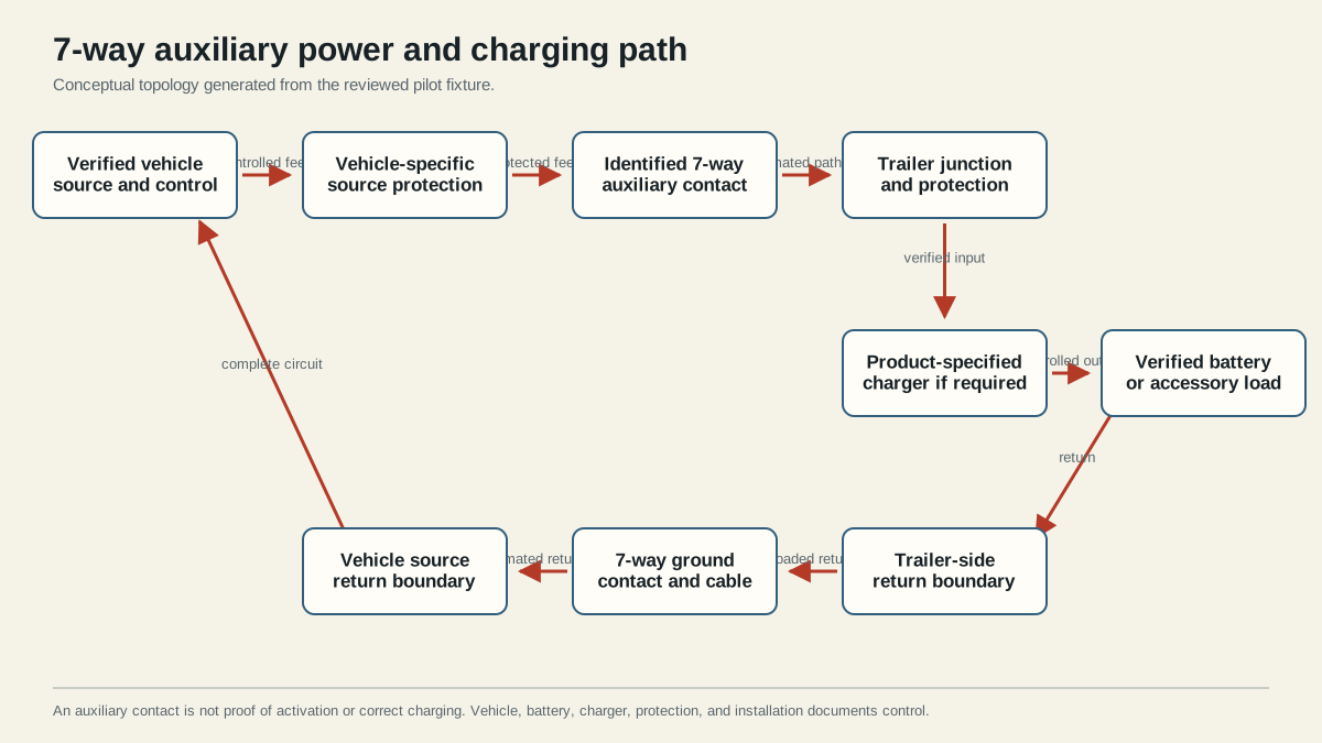
Mark each physical boundary on the drawing and on the trailer: vehicle fuse or module, socket wire entry, plug terminals, cable strain relief, junction box, protective device, charger input and output if fitted, battery positive boundary, battery negative boundary, frame bonds, and connector return. Note adapters and disconnects because each adds contacts and may change the available functions. A passive adapter cannot create an auxiliary source absent at its input.
The positive feed and return must be evaluated together. An open or restricted return can produce the same failed-load symptom as a restricted feed. A chassis bond can be an intentional part of the design, but the hitch ball, coupler contact, safety chains, or incidental frame contact are not a documented substitute for the connector return. Use the ground troubleshooting guide when the voltage difference appears on the return side under load.
Also separate circuit ownership. A small breakaway battery and its charger support emergency brake operation according to the installed kit; they are not automatically a house-battery supply. A house battery may support lights, pumps, refrigeration controls, an inverter, or other loads with very different duty cycles. An auxiliary accessory may be intended to operate only while connected. Do not combine these paths merely because they share a junction box or battery-shaped component.
Before testing, complete this map:
| Boundary | Evidence to record | Unresolved condition that stops the conclusion |
|---|---|---|
| Vehicle source/control | Manual section, operating state, module/factory equipment | Source logic or allowed use unknown |
| Source protection | Responsible device and protected conductor | Missing, bypassed, repeatedly operating, or unidentified protection |
| Connector | Family, half, view, molded labels, contact condition | Orientation or function assignment uncertain |
| Trailer feed and return | Route, material, length, junctions, adapters, frame bonds | Chafe, heat, corrosion, unsupported cable, or unknown splice |
| Charger/isolation | Exact model, mode, control/BMS input, installation instructions | Product compatibility or configuration unknown |
| Battery/load | Chemistry, arrangement, condition, manual, simultaneous loads | Damaged battery, unknown chemistry, or undocumented load |
Measure behavior under the intended load
An open-circuit meter draws very little current, so it can show a plausible voltage through a path that collapses when the real load operates. The objective is not to chase a universal number. It is to compare successive boundaries in the same documented operating state against the limits supplied by the responsible vehicle, charger, battery, connector, and protection documentation.
Prepare a test record before energizing anything:
| Record field | Why it matters |
|---|---|
| Vehicle and source state | Prevents an ignition-off, engine-off, module-off, or intermittent state from being compared with an engine-running test |
| Battery chemistry, condition, and starting state | Charging behavior changes with the battery and state of charge |
| Charger or load model and commanded state | Separates an inactive control input from a missing power source |
| Meter reference and probe points | Makes feed and return readings comparable and prevents connector-view mistakes |
| Simultaneous trailer loads | Exposes interaction that an isolated no-load test hides |
| Protection or module messages | A protection response is evidence, not permission to enlarge or bypass a device |
Proceed only if the intended load or charger is already approved for the mapped circuit. With the trailer disconnected, reproduce the documented vehicle state and confirm the socket result. Connect the trailer with sources off as required by the equipment instructions, then reproduce the same state. Observe the intended load or charger without opening protected enclosures or probing unsafe locations.
Measure from a stable source reference to the first accessible feed boundary, then across successive feed boundaries. Repeat on the return side while the symptom or charge state is present. Change only one state at a time. If a material change appears across one connector, junction, conductor, protection device, or return bond, inspect that boundary rather than replacing the battery or charger from the symptom alone.
Interpret common evidence patterns cautiously:
- No source at the disconnected socket points back to vehicle activation, protection, equipment, or documentation; it does not point to the trailer battery.
- Source present disconnected but absent with an approved load points to source control, protection, feed, return, connector, or load interaction; it does not justify a larger fuse.
- Stable charger input with no charger output may reflect charger mode, remote enable, engine detection, BMS permission, temperature, battery state, or a product fault. Use that charger’s diagnostics.
- A rising battery terminal voltage is evidence of changed battery conditions, not by itself proof of the correct charging profile or useful capacity recovery.
- Warmth, odor, swelling, arcing, repeated protection, or unstable readings are stop conditions, not test results to average.
The Victron Orion XS manual is useful as a product-specific evidence example: it distinguishes charger mode from power-supply mode and documents engine detection, input behavior, adjustable charging, protection, and battery settings. Those features demonstrate why a charger is a controlled system rather than a wire between two batteries. They do not mean that this model, its ratings, or its wiring is correct for a normal 7-way path.
Verify battery and charger requirements before connection
Decide the actual purpose before making a connection. “Charge the trailer battery” is too vague to own a safe design.
| Intended purpose | Documentation that controls | Minimum conclusion required before use |
|---|---|---|
| Maintain a breakaway battery | Breakaway kit, battery, brake, trailer, and applicable operating requirements | The specified charger and battery support the required breakaway test without house loads attached |
| Power an auxiliary accessory | Vehicle source, accessory, connector, conductor, and protection instructions | Source state, load behavior, return, and protection are compatible |
| Charge a house/service battery | Vehicle/alternator, battery, BMS, charger, isolation, and installation manuals | Charging profile, current control, source protection, temperature behavior, and isolation are explicitly resolved |
| Supply a charger input | Charger plus every upstream vehicle and wiring limit | Input remains inside the charger’s specified operating envelope under the recorded state |
A battery can require chemistry-specific voltage, current, temperature, and BMS behavior. A controlled charger can require its own input protection, output protection, conductor dimensions, ventilation, mounting, remote enable, and isolation logic. The charger manual used in this research explicitly directs the installer to configure the correct charging algorithm before connecting a battery and to follow battery-manufacturer specifications. Apply that principle to the exact products installed, not to the example manual’s values.
Breakaway operation remains independent safety work. Follow the installed kit and brake manufacturer’s procedure and use the breakaway wiring diagram to distinguish the emergency battery/switch path from normal controller output. Do not drain, repurpose, bypass, or casually parallel a required breakaway battery to support house loads. A passing auxiliary-power measurement does not certify breakaway operation.
Before closing the job, record the connector view, source state, vehicle protection and control, every feed and return boundary, battery identity, charger mode and settings, BMS or isolation behavior, loaded measurements, and product-specific pass criteria. Restore seals, covers, strain relief, supports, and abrasion protection. Recheck required lighting, normal braking, and breakaway functions whenever the work touched shared connectors, grounds, junctions, or batteries.
The final pass statement should be narrow: the identified source and return supported the approved installed load in the documented state, and the exact battery/charger system met its own criteria. If any required input is missing, label the system unverified and use qualified vehicle or trailer electrical help. The power and grounding guide remains the ownership map for related lighting, brake, breakaway, auxiliary, and house-battery circuits.