
Testing a trailer plug is most useful when it answers one question: does the fault begin before the connector, at the connector, or after it? A meter reading without that boundary can be misleading. Start by identifying the installed connector and viewing direction, disconnect the trailer for vehicle-side output checks, operate one function at a time, and record what the test proves.
Safety limit: Secure the vehicle and trailer before testing. Keep probes from bridging adjacent contacts. Follow the vehicle, connector, trailer, brake-controller, and lamp instructions. Do not energize an unknown auxiliary or brake contact, bypass a fuse, test a damaged or hot connector, or tow with required lighting, braking, or breakaway evidence unresolved.
Identify the connector and select a safe reference
Count and name the connector family before looking for a pinout. A four-way flat, five-way flat, six-way round, seven-way RV blade, and seven-round connector are different physical families. “Seven pin” alone does not identify the housing, view, or installed function. The pinout lookup shows why the vehicle and trailer sides can mirror each other.
Record four facts: connector family, vehicle or trailer side, front/mating or rear/wire-entry view, and the function you intend to test. Then compare the installed housing, key, labels, service manual, and wiring records. A typical color convention is only a starting reference; a previous repair, adapter, factory module, or nonstandard trailer can change the installation.
For a lighting test, the safe first reference is normally the disconnected tow-vehicle socket. CURT’s wiring and installation reference likewise separates connector identification from function testing. For a brake, auxiliary, reverse, or charging circuit, use the vehicle and controller documentation before applying a test load. Do not probe a position merely because a diagram places a familiar function there.
Test ground and one source function at a time
Turn off commands before connecting the tester. Inspect for looseness, corrosion, pushed-back contacts, damaged insulation, and evidence of heat. Use the tester type and reference method specified for the equipment. A continuity check can identify an open path, but it does not prove that a return can carry the operating load.
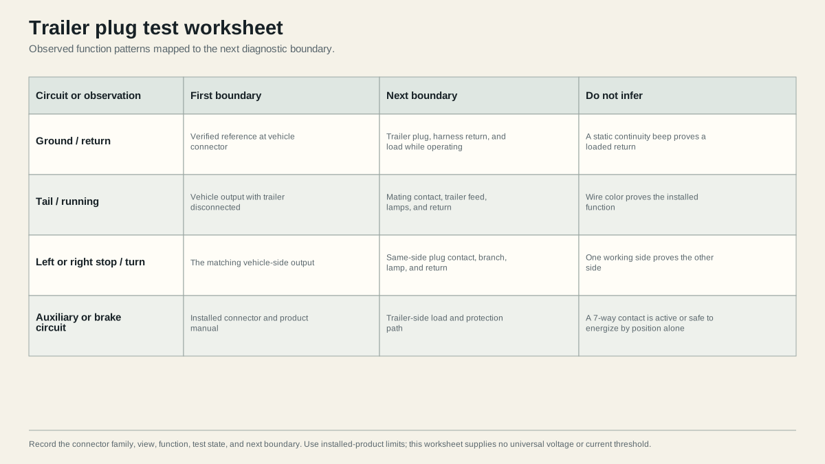
For vehicle-side lighting, test the ground reference and then operate one command: tail/running, left stop/turn, or right stop/turn. Keep the trailer disconnected. Record whether the expected source behavior is present and stable. A failed vehicle output owns the next step: follow the vehicle manual for its fuse, converter, module, harness, and switch path.
If the vehicle output passes, inspect and test the mating boundary. A clean reading on an open connector does not prove contact under load. If the function disappears at the trailer plug, inspect the contacts and plug strain relief. If it reaches the plug, continue to the trailer feed, branch, lamp, and return.
Record results by circuit rather than wire color
Use a small table for every function:
| Function | Vehicle socket, trailer disconnected | Mating boundary | Trailer/load result | Next owner |
|---|---|---|---|---|
| Ground/return | Reference selected and stable | Contact and return inspected | Return observed while the load operates | Vehicle or trailer return path |
| Tail/running | Output present when commanded | Same function reaches plug | Lamps and branch operate | Tail feed, lamp, or return |
| Left stop/turn | Left output present | Left contact passes | Left lamp and branch operate | Left vehicle output or trailer branch |
| Right stop/turn | Right output present | Right contact passes | Right lamp and branch operate | Right vehicle output or trailer branch |
| Auxiliary/brake | Manual-defined test only | Product-defined contact | Load and protection path verified | Vehicle/controller or trailer system |
Write the connector view and the tester reference beside the result. Do not convert “voltage present” into “circuit good” unless the applicable procedure defines the test conditions. A high-impedance meter can show a source through a backfeed or weak connection. Conversely, a test lamp or load can change the circuit state. Use the instrument and loaded test described by the installed documentation.
When a second function changes the first, reproduce the interaction and test feed and return boundaries while the symptom is present. Dim lamps, flicker, cross-illumination, or a function that works only disconnected point toward a load-dependent restriction, shared return issue, converter behavior, or protection/control issue; it does not automatically prove a bad lamp.
Use the result to choose the vehicle or trailer path
The result should name the next boundary, not a replacement part:
- Vehicle output fails with the trailer disconnected: remain on the vehicle-side path. Check the vehicle manual for fuses, modules, converters, switches, and compatibility.
- Vehicle output passes but the plug does not: inspect the socket, terminal retention, corrosion, adapter, and cable entry.
- Plug passes but the trailer branch fails: divide the trailer harness at documented junctions and compare the last working with the first failed point.
- The function works unloaded but fails when operating: measure the feed and return under the symptom using equipment-specific limits.
- An auxiliary, brake, or charging contact is unknown: stop and identify the connector and product documentation before energizing it.
Required lighting, braking, and breakaway failures are stop conditions until the applicable repair and functional test pass. Restore covers, seals, strain relief, and connector locks after testing. Record the repair, retest the original function, and then check the other required functions so a new contact or ground change has not created a second fault.
This procedure deliberately does not publish one pin voltage, fuse, wire size, or color rule for every trailer. The installed connector standard, vehicle module, controller, adapter, lamp, load, and jurisdiction control those details. The value of the worksheet is narrower and more reliable: it tells you where to test next and what your current evidence still does not prove.