A safe utility-trailer rewire starts with an inventory, not a color chart. Confirm that the task is a basic North American 4-way lighting system, identify every required lamp, map the connector and viewing direction, plan the physical route and complete return path, and test each function before closing the loom. If the trailer needs electric brakes, reverse, auxiliary power, or another independent circuit, a four-position connector is not the complete design.
Safety and scope limit: Secure the trailer against movement and disconnect electrical sources as the installed equipment requires. This guide does not select conductor size, fuse or breaker rating, splice product, lamp equipment, or legal configuration for every trailer. Stop for unidentified circuits, damaged structure, heat, arcing, repeated protection operation, required brakes or breakaway equipment, or lighting requirements that cannot be confirmed.
Define the trailer and required lighting scope
Record the trailer manufacturer, model, year, identification plate, width and length information, axle and brake equipment, connector family, lamp part numbers, and any modification. Photograph the existing connector, junctions, branches, lamp mounts, frame bonds, tilt or folding points, and damaged areas before removing anything. Labels and prior wiring records are evidence even when the old harness no longer works.
A basic four-way interface carries four functions: ground/return, tail or running lamps, left combined stop/turn, and right combined stop/turn. It does not provide an independent electric-brake output, battery charge line, or reverse circuit. Use the connector types guide if the installed body or required functions do not match that scope.
Required lighting is not determined by the plug alone. Trailer dimensions, configuration, manufacture, use, and jurisdiction can change which tail, stop, turn, marker, clearance, identification, license, or reflector equipment applies. NHTSA’s FMVSS No. 108 interpretation illustrates why a lamp’s function and installation context matter. Confirm the requirements that apply before buying a harness kit or drilling mounting holes.
Create a pre-work inventory:
| Item | Record before removal | Stop condition |
|---|---|---|
| Connector | Family, vehicle/trailer half, front/rear view, molded labels | Family or viewing direction is uncertain |
| Lamps and reflectors | Function, side, location, mounting and return method | Required equipment cannot be identified |
| Existing harness | Junctions, colors, labels, damage, route and branch points | Unknown wire may serve brakes, power, or another system |
| Return path | Dedicated wires, designed frame bonds, connector ground | Hitch ball or accidental metal contact is the only apparent return |
| Structure and route | Sharp edges, hinges, tilt points, suspension and heat exposure | Safe supported route is unavailable |
Plan harness branches protection and return paths
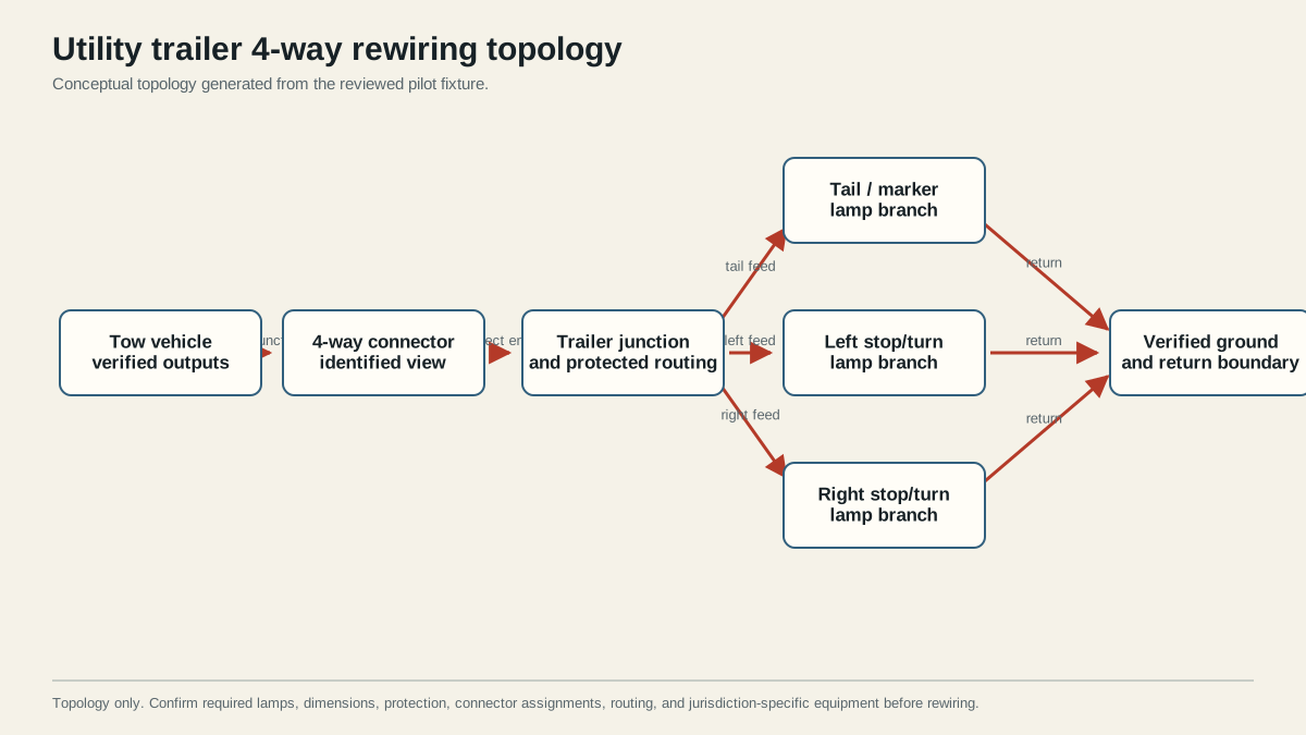
Draw the circuit before installation. Begin at verified tow-vehicle outputs, cross the identified 4-way connector, enter a serviceable trailer junction, and split into the tail/running branch plus the left and right stop/turn branches. Draw the return from every lamp and junction back through the trailer plug and vehicle source. Do not use insulation color as the only label.
Plan physical routing separately from the electrical drawing. Identify protected paths inside frame members or approved loom, entry and exit grommets, service loops, junction-box strain relief, support spacing, water-exposed areas, and transitions that move. Keep wiring away from sharp edges, exhaust heat, suspension travel, pinch points, cargo contact, and places where a tilt bed or folding tongue can stretch it.
The return is part of each working circuit. A lamp grounded through mounting hardware depends on the lamp base, fastener, coating, frame joints, main bond, connector contact, and vehicle return. A lamp with a dedicated return wire still depends on every splice and connector boundary. Choose the method supported by the lamp and trailer design, then make every intended bond explicit on the plan.
Protection and conductor sizing require actual inputs: simultaneous lamp load, conductor material and length, route temperature, terminals, source and converter limits, environmental exposure, and applicable product instructions. A universal online gauge or fuse value cannot replace those inputs. Use CURT’s trailer wiring reference for common function conventions, then use the installed equipment documentation for the finished design.
Terminate and support the wiring
Verify that every source is off or disconnected as required. Label the old circuits before removal. Remove abandoned splices, unsupported cable, corroded terminals, and damaged insulation only after proving that they are not part of brakes, breakaway, auxiliary power, or another system. Preserve useful labels and photographs in the work record.
Work from stable boundaries:
- Mount or retain the correct trailer-side connector with adequate strain relief and a protected cable entry.
- Route the main harness to an accessible junction rather than burying unexplained branch splices in loom.
- Label the ground, tail/running, left stop/turn, and right stop/turn conductors by verified function.
- Route each branch along the planned protected path, leaving only the service movement specified for the component.
- Prepare conductors and terminals with the tools and dimensions required by the selected connector or splice system.
- Establish each lamp return and the main return boundary without relying on the coupler or hitch ball.
- Support and protect the harness, but keep junctions accessible until functional testing passes.
Do not twist and tape a connection as a finished repair. Do not place an exposed splice where water can pool. Do not trap a ring terminal over paint or corrosion and assume fastener pressure creates a reliable bond. Do not enlarge a fuse to stop repeated operation. Each of those actions can hide the evidence while leaving the failure mechanism in place.
After terminating one branch, check it against the drawing before proceeding. Confirm conductor identity at both ends, mechanical retention, insulation support, sealing, polarity where the lamp requires it, and the planned return. This staged check catches a crossed branch before every wire is wrapped together.
Test every required function and stop on any failed result
First test the tow-vehicle connector with the trailer disconnected using the trailer-plug procedure. Confirm connector family and view, select the documented reference, and operate one lighting command at a time. A failed source output remains a vehicle-side problem; do not alter the new trailer harness to compensate.
Connect the trailer and test the same four functions. Record results instead of writing only “all lights work”:
| Test state | Expected evidence | If it fails |
|---|---|---|
| Tail/running alone | All applicable tail, marker, clearance and license branches operate consistently | Trace tail feed and return from connector to first failed boundary |
| Left stop/turn | Correct left lamps operate without right-side cross-action | Compare left source, contact, branch, lamp and return |
| Right stop/turn | Correct right lamps operate without left-side cross-action | Compare right source, contact, branch, lamp and return |
| Stop command | Both applicable stop sides respond as the vehicle/converter design requires | Test both disconnected vehicle outputs before reopening trailer wiring |
| Combined functions | No dimming, flicker, unintended glow or module fault | Test feed and return under the reproduced load |
| Stationary movement check | Connector and harness remain stable when gently inspected | Repair retention, chafe, or intermittent boundary before towing |
Use the 4-pin diagram to confirm orientation and function, and the lighting diagnostic tree if a result still crosses several possible boundaries. Change one variable at a time. A correct open-circuit reading does not prove that a connection can support the operating lamps, so reproduce load-dependent symptoms while measuring the relevant feed and return boundaries.
Close junction boxes and loom only after all tests pass. Restore grommets, seals, strain relief, supports, abrasion protection, and service loops. Record the final connector view, branch labels, return method, product instructions, test states, and any requirement that remains unresolved.
Do not tow when a required lamp is absent, intermittent, incorrectly assigned, dim from an unresolved fault, or affected by another command. Also stop for hot terminals, damaged insulation, repeated fuse or module protection, an unidentified circuit, or a return path that has not been verified under the applicable load. A successful rewire is not the neatest bundle; it is a documented circuit whose required functions remain stable in every relevant test state.