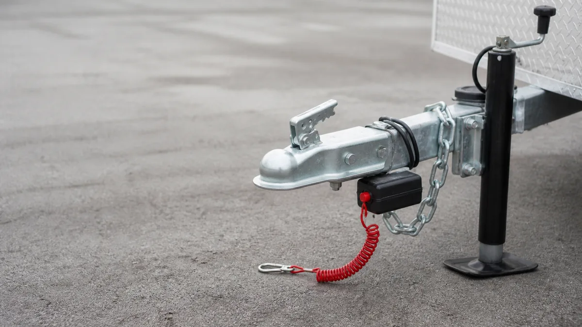
There is no safe universal breakaway pull test. First identify the brake technology, breakaway kit, battery, charger, switch, controller, and controlling manuals. Then use the connection state, battery preparation, activation duration, observation, reset, and recharge steps specified for that exact combination.
The electric trailer brakes system guide explains which downstream components the normal and emergency sources share. This procedure owns only the breakaway functional test.
This matters because the breakaway path can interact with other equipment. The CURT 52044 kit instructions and Tekonsha Prodigy P2 controller instructions both require disconnecting the trailer electrical plug from the tow vehicle for the covered breakaway test. Another system can define a different process. Never splice the best-looking steps from several manuals into a new procedure.
Safety limit: Chock and secure the trailer before testing. Do not tow unless the normal service brakes and required breakaway system both pass their own procedures. Do not use the breakaway cable as a parking brake. Stop for a damaged or leaking battery, burned connector, hot wiring, repeated protection-device operation, damaged cable or switch, incomplete brake response, or an unidentified system.
Identify the brake and breakaway system type
A breakaway system is an emergency source intended to apply the trailer brakes if the trailer separates from the tow vehicle. In a typical electric-drum arrangement, a charged battery on the trailer supplies the brake circuit when removal of the switch pin closes the emergency path. The downstream brake feed, parallel branches, magnets, and return can overlap the normal service-brake circuit.
Do not assume every braked trailer uses this arrangement. Identify:
- electric drum, electric-over-hydraulic, hydraulic surge, or another brake technology;
- axle and brake manufacturer, model, size, and number of braked wheels;
- breakaway kit, switch, battery, charger, and test-panel model;
- tow-vehicle brake controller and its compatibility with the installed technology;
- connector family and verified function mapping;
- trailer and vehicle instructions;
- laws and inspection rules that apply to the trailer’s weight, class, use, and jurisdiction.
If any identity is missing, stop before pulling the pin. Photographs, labels, part numbers, wiring records, and manufacturer support can establish the correct manual. Appearance or wire color alone cannot.
The breakaway switch wiring diagram explains the conceptual battery, switch, brake-feed, and return topology. Use it to understand boundaries, not as an installation or test specification.
Separate normal braking from emergency braking
Normal service braking begins at the tow-vehicle controller. Breakaway braking begins at stored energy on the trailer. A successful normal-brake check does not prove the battery, charger, switch, cable, or emergency path. A successful breakaway actuation does not prove controller input, modulation, normal connector output, or road performance.
Record both independently:
| Path | Source | Activation | Minimum result to document |
|---|---|---|---|
| Normal service braking | Tow vehicle and brake controller | Pedal and controller behavior under their instructions | Correct controller status and complete brake response under the normal procedure |
| Breakaway braking | Trailer battery or other specified stored-energy source | Switch and cable under the kit procedure | Product-defined battery readiness, switch actuation, required brake response, reset, and restoration |
Dexter’s electric-brake manual depicts a breakaway battery supplying the brakes through a breakaway switch and describes the electric brake assemblies as parallel loads in its covered system. That architecture supports testing every required brake response, not accepting a sound or display alone.
Treat regulatory statements as scoped requirements
49 CFR Part 393 includes breakaway and emergency-braking requirements for vehicles subject to that federal commercial-motor-vehicle part. The section is not a universal rule for every private trailer. Requirements can differ with jurisdiction, vehicle type, weight, use, and date. Check the controlling law for the actual combination instead of copying a threshold from an unrelated vehicle class.
Inspect cable switch battery and charger
Perform the applicable pre-test inspection before changing the switch state. Keep the pin fully seated unless and until the manual calls for removal.
Cable and attachment
Inspect the cable for fraying, kinks, corrosion, broken fittings, tangles, or a path that can snag. Confirm the switch is secure, aligned as required, able to pivot if its instructions require, and free from physical damage. The cable must reach its specified independent attachment point through the full articulation of the combination without pulling during normal turns or becoming too slack to operate during separation.
The CURT 52044 instructions prohibit attachment to the trailer ball, safety chains, or certain mounting hooks for that kit and define a suitable tow-vehicle frame location. Follow the exact installed kit. Do not infer that an attachment method from one product is approved for another.
Switch and wiring
Inspect the switch body, pin, seals, leads, splices, routing, strain relief, junctions, and brake-feed connection. Look for chafe, pinching, exposed conductor, corrosion, heat damage, poor support, and contact with moving or sharp parts.
Trace function rather than color. CURT notes that trailer brake-circuit and auxiliary-power colors can vary. A previous repair may also have changed them. Verify battery positive, battery negative or return, charger input, switch path, brake feed, and return against the installed manual before altering a conductor.
Battery and charger
Inspect for swelling, leakage, cracks, loose terminals, corrosion, an unsecured case, water entry, or damaged wiring. A damaged battery is a stop condition. Use the kit’s product-defined test method, charge indication, charger procedure, and replacement specification.
A push-to-test light is one observation, not proof of the complete system. It may report a battery state under a particular internal test but does not prove the switch closes, wiring carries the load, every brake responds, or the battery sustains the manufacturer-required duration. Record exactly what the indicator means in the kit instructions.
Do not substitute a generic resting-voltage number or charger time. Battery chemistry, capacity, state-of-charge method, charger design, temperature, storage history, and the kit’s test load all matter. The installed product defines pass.
Run the manufacturer-specified functional test
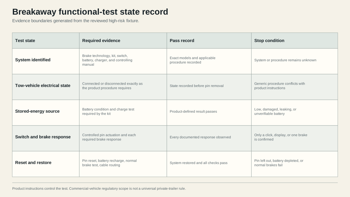
Copy the product procedure into the service record before starting. Mark each instruction as a state or observation: connection state, trailer support, battery preparation, pin action, brake response, allowed duration, pin reset, battery recharge, and final normal-brake check.
For the CURT 52044 kit, the current instructions explicitly say not to perform the post-installation test while the seven-way is connected to the tow vehicle. They specify safely lifting the trailer with jack stands so wheels can rotate, spinning a wheel, pulling the switch pin, checking that the wheel stops and remains unable to rotate for the stated test, reinserting the pin, lowering the trailer safely, and recharging the battery afterward. Those details apply to that kit and installation, not every breakaway system.
Tekonsha’s Prodigy P2 instructions separately warn that the trailer plug must be disconnected from the tow vehicle before testing a breakaway switch because the covered controller may be damaged. This controller requirement remains relevant even when the breakaway-kit label is difficult to read. If product instructions conflict or the installed combination is uncertain, do not test until the manufacturers clarify the compatible procedure.
A bounded execution record
Use this order, replacing each placeholder with the exact manual instruction:
- Secure: Park on the specified surface, prevent movement, isolate people and traffic, and use only approved lift and support points if the procedure requires raised wheels.
- Identify: Record every product and manual revision. Confirm brake technology and controller compatibility.
- Set connection state: Connect or disconnect the tow-vehicle electrical plug exactly as both the kit and controller instructions require. Record the state before touching the pin.
- Prepare stored energy: Perform the kit-defined battery test or charging step. Record its actual indicator or measured result and pass criterion.
- Inspect: Confirm cable, attachment, switch, pin, battery case, wiring, junctions, brake circuit, and return are physically ready.
- Activate: Pull or actuate the pin only by the approved method and only for the specified duration.
- Observe: Check every response the manual requires. Do not accept a click, illuminated display, current reading, or one stopped wheel as a substitute for all required results.
- Reset: Reinsert the correct pin fully, confirm switch restoration, and verify the brakes release under the product procedure.
- Restore: Recharge or service the battery as required, close covers, secure wiring, route and attach the cable correctly, and perform the required normal-brake test.
Never leave the switch activated longer than the applicable instructions allow. Continued brake current can discharge or damage a battery and heat magnets, wiring, or other equipment. Never tow with the pin removed or use breakaway activation to hold a parked trailer.
Interpret failures by layer
| Failed observation | Unresolved layer | What to do next |
|---|---|---|
| Product battery check does not pass | Battery, charger, supply, connection, or test circuit | Stop and follow the kit’s battery diagnostic and replacement procedure |
| Battery passes but switch activation produces no brake response | Switch, wiring, brake feed, return, or downstream brakes | Keep trailer out of service and isolate the first failed boundary |
| Only some brakes respond | Parallel branch, local return, magnet or actuator, or mechanical assembly | Diagnose the differing branch under the brake manual |
| Brakes apply but do not release after pin reset | Switch reset, unintended feed, wiring, controller interaction, or mechanical drag | Disconnect only as the manuals permit and obtain qualified diagnosis |
| Wiring or battery becomes hot, smells, smokes, leaks, or opens protection | Short, overload, damaged component, wrong connection, or incompatible equipment | Stop immediately and make the system safe without bypassing protection |
The trailer brakes not working guide owns downstream electrical and mechanical layer isolation. Do not use higher controller gain to repair a failed breakaway battery or switch.
Record results and block towing on failure
A breakaway system passes only when every item required by the controlling product procedure passes and the system is restored for towing. Your record should contain:
- test date and operator;
- tow vehicle, controller, trailer, brake system, breakaway kit, battery, charger, and switch identities;
- manual titles, document numbers, revisions, and URLs;
- tow-vehicle electrical connection state during each step;
- battery preparation and product-defined result;
- cable, attachment, switch, wiring, and case inspection results;
- each required wheel, brake, actuator, pressure, or other response;
- activation duration and reset result;
- recharge or restoration completed;
- normal service-brake result after restoration;
- defects, repairs, and unresolved variables;
- explicit pass or out-of-service decision.
Do not record “breakaway works” when only the pin clicked or one wheel resisted turning. State exactly what was observed. A later pre-trip check should be able to distinguish battery readiness, switch function, downstream brake response, and normal brake operation.
Stop and obtain qualified help when needed
Keep the trailer out of service when the correct procedure is unavailable, product identity is uncertain, manuals conflict, the battery fails or is damaged, the switch or cable is defective, any required brake does not respond, the system does not reset, normal braking fails after the test, or wiring and protection show distress.
Qualified service is appropriate when the test requires lifting without rated equipment, an electric-over-hydraulic or other actuator procedure is unclear, battery or charger specifications are unknown, a controller may have been backfed, brake assemblies require opening, or legal applicability is uncertain. A disclaimer cannot convert an unverified system into a passing one.
Before towing, fully seat the pin, close and secure the battery enclosure, restore charge, protect the wiring, attach the cable at the product-approved point, connect the normal trailer plug, and verify normal service braking. The emergency path and normal path must each pass their own checks.
Sources
- CURT 52044 breakaway-kit instructions
- Tekonsha Prodigy P2 instructions
- Dexter electric-brake service manual
- 49 CFR Part 393
Last verified: August 26, 2026.