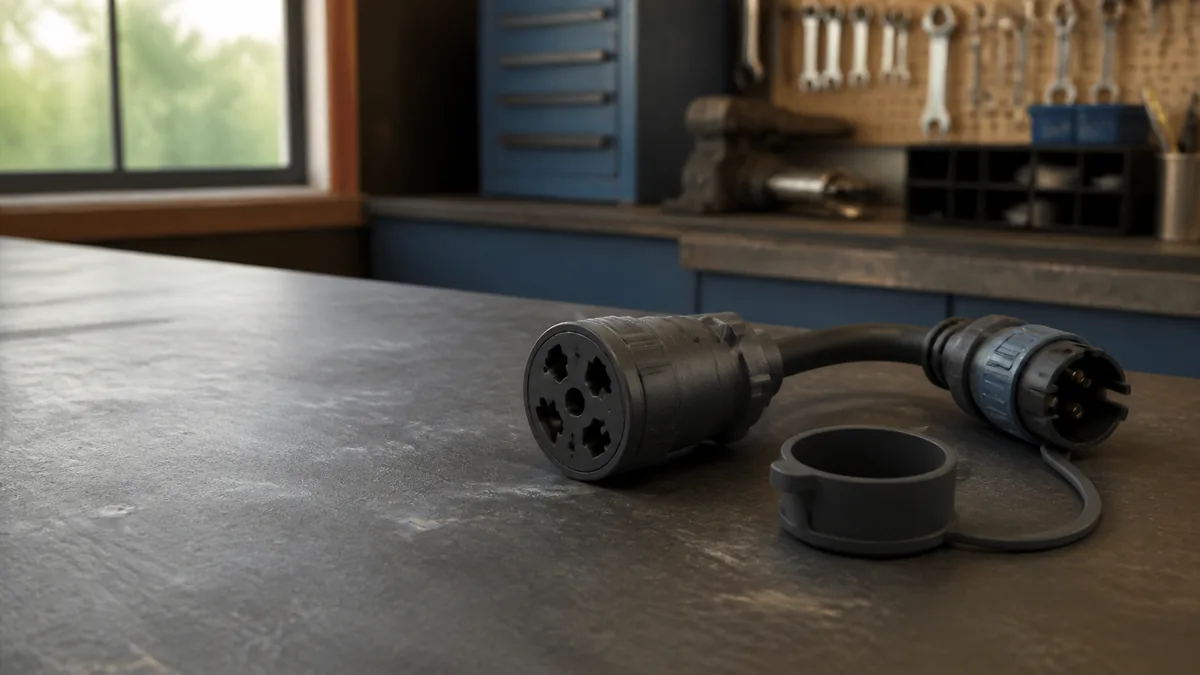
What must your 7-way outlet operate?
A basic 4-way input already carries tail/running, left stop/turn, right stop/turn, and ground. Select any additional functions you need.
An adapter changes the connector interface; it does not create brake-controller output, fused auxiliary power, or a reverse feed. Add each required circuit using the adapter and vehicle instructions, then verify functions with a tester.
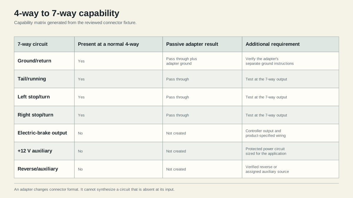
A 4-way to 7-way adapter can pass the four circuits already present at the vehicle: ground, tail/running, left stop/turn, and right stop/turn. It cannot generate electric-brake output, +12 V auxiliary power, or reverse. Those 7-way positions stay inactive until the vehicle provides separate verified inputs.
Inventory the circuits present at the vehicle
Disconnect the trailer and verify the vehicle 4-way by function. Command running lamps, left turn, right turn, and brake lamps one at a time with a known-good tester ground. Inspect the housing and contacts. An adapter cannot repair an upstream missing or intermittent signal.
Confirm that the selected adapter is intended for the actual vehicle and connector families. Product leads and grounding instructions vary.
Use this inventory before buying or wiring anything:
| Vehicle-side circuit | How to prove it exists | What the adapter may do with it |
|---|---|---|
| Ground/return | Use the adapter manufacturer’s specified ground point and verify the return under load | Pass the four lighting returns and any separately added circuits |
| Tail/running | Turn on the vehicle lamps and test the assigned 4-way terminal | Route it to the matching 7-way lighting position |
| Left stop/turn | Command left turn, then service brakes | Route the combined left signal to the matching position |
| Right stop/turn | Command right turn, then service brakes | Route the combined right signal to the matching position |
| Brake-controller output | It is not present at a normal 4-way; identify the controller output lead separately | Route a separately installed and verified output to the 7-way brake position |
| +12 V auxiliary | It is not present at a normal 4-way; verify a separate protected source | Route that source to the assigned auxiliary position |
| Reverse/auxiliary | It is not present at a normal 4-way; verify the intended vehicle signal | Route that separate signal to the assigned position |
A 7-way receptacle on the bumper proves only that seven contact positions are available. It does not prove that the three added positions are connected or usable.
Compare those circuits with the trailer requirements
CURT’s 57184 adapter page identifies the 4-way input and 7-way output, lists the extra 7-way functions, and states that manual wiring is required. Follow the instructions for the exact adapter installed.
Adapter-only versus completed conversion
These two installations can look identical from outside:
- Adapter-only: the four lighting functions pass from the existing 4-way. The other positions are inactive.
- Partially wired adapter: lighting passes and one or more loose leads have been connected, but every added function still needs its own verification.
- Completed 7-way conversion: the lighting circuits, ground, controller output, protected auxiliary feed, and any reverse assignment required by the trailer have been installed according to the applicable product and vehicle instructions.
The word “adapter” therefore does not answer whether trailer brakes work. A passive shell cannot synthesize controller output. Some adapter kits expose a brake-output lead that can be connected to an already installed compatible controller; that is additional wiring, not a function created from the four input circuits.
Identify the extra connections needed for missing functions
Use the helper above to list required functions. Electric brakes need a compatible installed controller and its specified output path. Auxiliary power needs a protected source designed for the intended load. Reverse needs a verified vehicle signal. Ground must follow the adapter instructions and support the combined return path.
Do not use this page to choose conductor size, protection, controller setup, or charging design. Those depend on the vehicle, controller, adapter, trailer loads, run length, and applicable product limits.
Decide from the trailer’s actual requirements
| Trailer requirement | Adapter-only result | What must be added or verified |
|---|---|---|
| Base lighting only | Usually sufficient after all four functions pass testing | Correct ground, connector orientation, and stable lighting under load |
| Electric brakes | Not available from the four lighting inputs | Compatible controller, controller output wiring, connector assignment, and functional brake checks |
| Breakaway battery maintenance | Not established by the adapter shell | Product-specified charging path and protection |
| Trailer battery or accessory power | Not established by the adapter shell | Vehicle and trailer charging design appropriate to the equipment |
| Reverse lamps or surge-brake lockout | Not available from the four lighting inputs | Verified reverse or assigned auxiliary input |
Do not treat a +12 V auxiliary position as a universal battery charger. A present voltage reading says nothing by itself about current capacity, protection, isolation, or compatibility with the battery and charger on the trailer.
Test every required function before towing
After installation, test each required function at the 7-way socket, then with the trailer connected and stationary. An unused position may remain inactive only if the trailer does not require it. Verify brake operation using the controller and axle manuals, and verify auxiliary or reverse loads using their product instructions.
Use a two-stage acceptance test. First test the disconnected vehicle receptacle so a trailer fault cannot hide a missing source. Then connect the secured trailer and repeat the required lighting, brake, reverse, and auxiliary checks under their normal operating conditions. Label any intentionally unused position.
If base lighting works but the brakes do not, do not start by rewiring the trailer plug. Confirm that the vehicle has a compatible controller, that it recognizes the trailer as required, and that its output reaches the assigned 7-way position. If the auxiliary position is dead, inspect the vehicle-specific fuse, relay, enablement, and wiring instructions instead of borrowing power from a lamp circuit.
Use the connector selector if the trailer’s required functions are still unclear. Stop before towing if any required circuit is absent, mislabeled, unprotected, intermittent, or inconsistent with product documentation.
Sources
- CURT 57184 4-way to 7-way adapter
- CURT trailer wiring reference
- Tekonsha brake-controller instructions
Last verified: August 25, 2026.