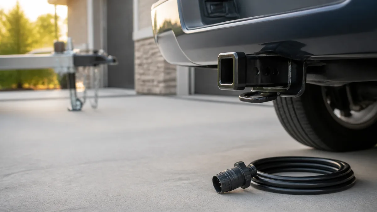
This reference covers a 7-way RV blade connector, viewed from the rear where wires enter the vehicle socket and trailer plug. It does not cover a 7-way round-pin connector. The positions shown are function positions; traditional and SAE J2863 wire colors are separate conventions.
Distinguish RV blade from round-pin connectors
An RV blade connector uses flat blade-style contacts in a keyed circular housing. A round-pin connector uses round contacts and must be identified with its own documentation. SAE J2863 defines a seven-position tow-connector interface, while manufacturers also publish application diagrams for their products.
Confirm the housing family, key position, connector half, and viewing direction. If any one of those is unknown, do not move conductors based on this page.
The name “7-pin” is not specific enough. In North American light-trailer use, people often use it for the keyed RV blade connector. Heavy truck and other round-pin interfaces also have seven contacts but use different housings, assignments, and governing documentation. Count contact style as well as contact quantity.
Before continuing, confirm all of the following:
- Seven flat blade-style contacts are present in a keyed circular housing.
- You know whether the part is the vehicle receptacle or trailer plug.
- You know whether the drawing shows the mating face or rear wire-entry side.
- Molded terminal labels or product instructions are available when a conductor will be moved.
Orient the vehicle socket and trailer plug
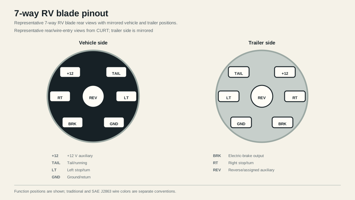
The diagram follows representative rear views published in CURT’s towing documentation. Hold the key at the top and compare the correct half. A mating-face view from the opposite side will appear reversed.
Why plug and socket drawings look mirrored
The vehicle receptacle and trailer plug face one another when mated. Viewed from behind, their corresponding contact positions therefore appear on opposite sides. Flipping a drawing in your head is a common way to place power on the wrong terminal.
Use one stable reference method: hold the correct connector half in the exact view named by the diagram, keep the key at the stated position, and follow a molded function label where available. If your documentation uses a front mating-face view, use that documentation directly instead of translating positions from this rear-view drawing.
Map seven circuit functions and convention variants
| Function | Role | Verification priority |
|---|---|---|
| Ground/return | Shared return path | Verify integrity under load |
| Tail/running | Tail, marker, clearance branch | Command running lamps |
| Left stop/turn | Left combined signal branch | Command left turn and brakes |
| Right stop/turn | Right combined signal branch | Command right turn and brakes |
| Electric-brake output | Proportional controller feed | Follow controller and axle manuals |
| +12 V auxiliary | Assigned power or charging feed | Verify source, protection, and product limits |
| Reverse/auxiliary | Reverse or assigned function | Verify actual installed assignment |
The CURT wiring guide shows both traditional and SAE J2863 color sets. That is a color-convention difference, not permission to assume a conductor’s function. Test and label the function first.
Keep wire color separate from contact position
CURT publishes these two common color-to-function conventions for RV blade wiring:
| Function | SAE J2863 example color | Traditional RV example color |
|---|---|---|
| Ground/return | White | White |
| Tail/running | Brown | Green |
| Left stop/turn | Yellow | Red |
| Right stop/turn | Green | Brown |
| Electric-brake output | Blue | Blue |
| +12 V auxiliary | Orange | Black |
| Reverse | Gray | Yellow |
This comparison explains why color alone is unsafe evidence. Green can mean right stop/turn in one convention and tail/running in another. Yellow can mean left stop/turn or reverse. Replacement cords and previous repairs may introduce still other colors.
Use this evidence order when identifying an installed circuit:
- Measured or traced electrical function.
- Molded terminal marking on the installed connector.
- Instructions for the exact connector, vehicle, controller, or trailer.
- A general color convention as a supporting clue.
Do not transpose the color columns into new physical pinouts. The contact function positions stay a separate layer from conductor color.
Verify the installed circuit before energizing it
With the trailer disconnected, test tow-vehicle lighting outputs one command at a time. Follow the installed brake-controller instructions and the electric trailer brake circuit reference for brake-output topology. Confirm auxiliary feeds with the correct load and protection information from the vehicle or product manual. Then trace the corresponding trailer conductors to their loads and returns.
Test by function, not by seven arbitrary probes
Start with the ground reference specified for the test equipment. Command running lamps, left turn, right turn, and service brakes separately. Confirm that only the expected positions respond. Follow the installed brake-controller procedure for its output; a generic static voltage check may not represent how that controller behaves. Check reverse only with the vehicle secured and according to the vehicle procedure.
For +12 V auxiliary, record whether power is always present, ignition-controlled, switched, or absent. Then confirm the vehicle-specific protection and intended use. Do not assume that a live terminal can charge any trailer battery or support any accessory.
After the disconnected receptacle passes, trace the trailer plug by function and inspect its junctions. Connect the secured trailer and repeat every function the trailer requires. If voltage is present unloaded but a lamp or brake circuit fails under load, test both feed and return paths for excessive loss.
Stop if the connector family or face is uncertain, a powered position conflicts with the expected function, the ground path is weak, protection is unknown, or a brake circuit fails its product-specific checks. Never use a general pinout to select fuse size, conductor size, controller settings, or battery charging limits.
Sources
- SAE J2863 automotive trailer tow connector
- CURT trailer wiring reference
- Dexter electric-brake service manual
Last verified: August 25, 2026.