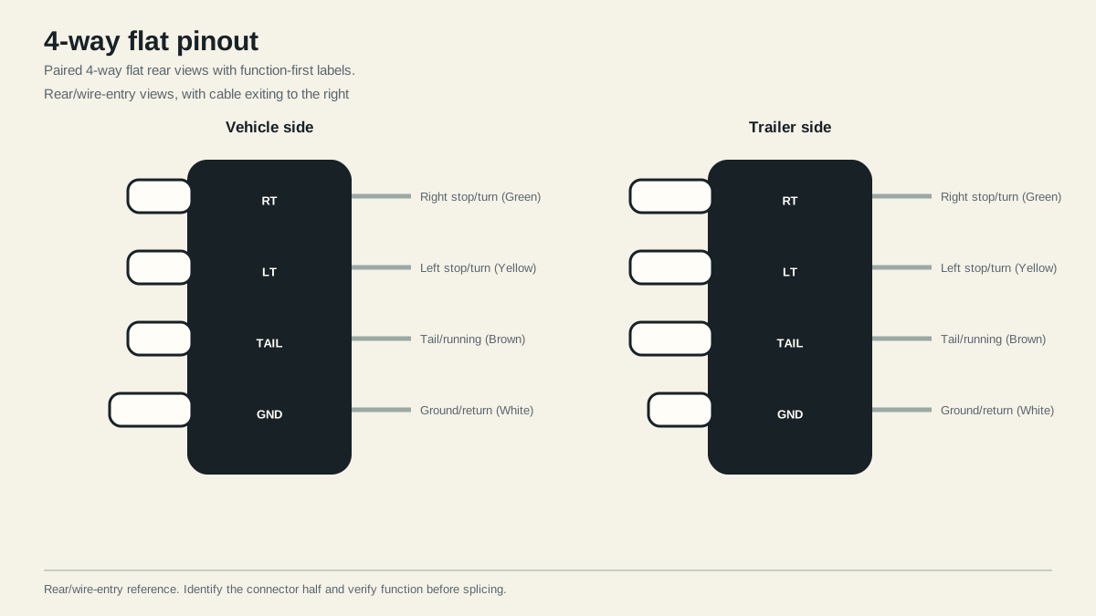
A typical North American 4-way flat carries four functions: ground/return, tail/running lamps, left stop/turn, and right stop/turn. The reference below shows rear wire-entry views. First identify whether you are holding the vehicle socket or trailer plug; the mating halves are easy to mirror mentally.
Confirm connector face and viewing direction
Set the disconnected connector in the same orientation as the drawing, with the cable exiting to the right. Confirm the housing shape and which contact is exposed. Do not rotate a front mating-face view and assume it matches a rear wire-entry view.
If the housing or view does not match, stop and identify it through the connector types guide. Repairing by color alone can move a signal onto the ground circuit or the wrong lamp branch.
Identify the half before reading left to right
On many 4-way flat sets, the tow-vehicle half is arranged so its powered contacts are recessed, while the trailer half has the complementary exposed and recessed shapes. Use the molded housing and the manufacturer’s documentation as the deciding evidence. Replacement ends and unusual products can differ.
Write down four facts before using any position diagram:
- Is this the tow-vehicle connector or trailer connector?
- Are you looking into the mating face or at the rear where wires enter?
- Which end of the housing is keyed or exposed?
- Is the diagram intended for this exact connector family?
Two correct drawings can appear reversed when one shows the mating face and the other shows the wire-entry face. That is a viewing-direction difference, not necessarily a disagreement about circuit function.
Map all four circuit functions
| Function | Typical color | What it should operate |
|---|---|---|
| Ground/return | White | Return path for all four-way loads |
| Tail/running | Brown | Tail, marker, and running lamp branch |
| Left stop/turn | Yellow | Left combined stop and turn branch |
| Right stop/turn | Green | Right combined stop and turn branch |
The CURT wiring guide documents this common function and color pattern. Existing repairs, replacement pigtails, and nonstandard wiring can differ.
Combined stop/turn means the left conductor carries both the left turn command and the left brake-lamp command, while the right conductor does the same on the right. The brown tail/running branch is separate and normally feeds tail, marker, and clearance lamps. White is commonly ground in this convention, but an installed conductor is not verified until its path or electrical function is tested.
The table is a function map, not a splicing instruction for every vehicle. Vehicles with separate amber turn lamps may use a converter module to create the combined trailer signals. Diagnose a missing vehicle-side output using that vehicle or converter documentation.
Test each circuit instead of trusting color alone
Disconnect the trailer. Establish a known-good ground for the tester, then command one tow-vehicle function at a time: running lamps, left turn, right turn, and brake lamps. Record the active terminal for each command. Reconnect only after the observed outputs match the intended functions.
On the trailer side, trace each terminal through its conductor to the expected load. A continuity check on an unpowered circuit can help identify a conductor, but a final functional test under normal load is still required because a weak connection can pass a low-current meter test.
Use a repeatable four-command test
| Command | Expected active lighting output | What an unexpected result suggests |
|---|---|---|
| Running lamps on | Tail/running only | Wrong assignment, backfeed, or shared return problem if stop/turn lamps also react |
| Left turn | Left stop/turn pulses | Connector, converter, or left branch fault if absent |
| Right turn | Right stop/turn pulses | Connector, converter, or right branch fault if absent |
| Service brakes | Both stop/turn outputs steady | Vehicle conversion or feed problem if only one or neither is present |
Keep the tester reference ground known and stable. Testing between an output terminal and an uncertain connector ground can make a good output appear dead. After the vehicle half passes, reconnect the secured trailer and repeat the same commands. A result that fails only when connected calls for loaded-circuit diagnosis, especially at the connector and return path.
Do not probe in a way that spreads terminals, punctures sealed insulation unnecessarily, or can short adjacent powered contacts. Use the test method specified for the connector and vehicle.
Recognize limits that require another connector
A 4-way has no independent position for electric-brake controller output, auxiliary power, or reverse. Do not borrow the ground or a lighting conductor for those functions. Choose a connector with enough independent positions and install the required protected circuits according to the vehicle and equipment instructions.
Common reasons to move beyond a 4-way include electric service brakes, a reverse-controlled surge-brake lockout, reverse lamps, or an auxiliary-power requirement. Count independent functions rather than assuming a larger trailer automatically needs a particular plug.
An adapter from 4-way to 7-way can make the connector bodies mate and pass these four circuits. The 4-way to 7-way capability guide explains why the other three 7-way positions remain inactive until separate vehicle-side circuits are installed.
Stop before towing if any required lamp is intermittent, a terminal is loose or corroded, the ground path is uncertain, or observed outputs conflict with the diagram.
Sources
Last verified: August 25, 2026.