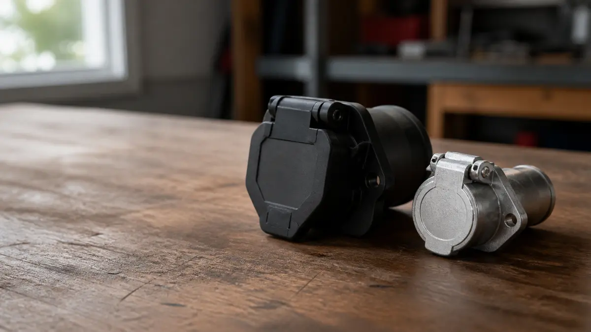
A 7-way RV blade connector and a 7-way round-pin connector are different physical families. The RV blade has six flat blade contacts around a center contact. The round-pin family uses seven round contacts. They do not mate directly, and a pinout for one must not be applied to the other.
The confusing part is language. Listings and conversations may call either one “7-pin,” “7-way round,” or simply “the round plug” because both housings are broadly circular. Identify the contact style and keying before selecting a diagram, adapter, replacement cord, or tester.
Compare terminal shape and arrangement
Use the disconnected connector face as the first piece of evidence. Clean only enough to see the contacts and molded markings using the connector instructions. Do not probe or disassemble an energized unknown connector.
7-way RV blade
Look for six flat, blade-like contacts arranged around one center contact inside a keyed circular housing. On the vehicle, this is commonly a covered receptacle. The trailer half is commonly a cabled plug. The word “RV” in the name describes the connector family; it does not prove the trailer is a recreational vehicle or that every available circuit is used.
The RV blade family commonly supports the four base lighting/return paths plus electric-brake output, auxiliary power, and reverse or another assigned auxiliary function. That is connector capacity, not proof of installed operation. A factory vehicle receptacle may have inactive positions, vehicle-specific fuses, configuration requirements, or controller dependencies.
7-way round-pin
Look for seven round contacts rather than flat blades. CURT publishes a separate 7-way round reference with a different physical drawing and placement. Retailer results also describe round-pin connectors as more common in some heavy-duty or equipment applications, but application stereotypes are not a pinout.
Round-pin systems can also differ by product family and governing convention. This page does not assign every round-pin contact. It identifies the family and routes the reader to the exact connector or equipment documentation. A North American light-trailer RV blade page is not a substitute for a commercial-vehicle, agricultural, imported, or proprietary round-pin standard.
Physical checklist
| Observation | RV blade evidence | Round-pin evidence | Still unresolved |
|---|---|---|---|
| Outer body | Circular, keyed | Circular, keyed | Key dimensions and product family |
| Outer contacts | Flat blades | Round pins or sockets | Vehicle versus trailer half |
| Center | One center contact | One of seven round contacts may be centered | Actual circuit assignment |
| Direct mating | Only with matching RV-blade half | Only with matching round-pin half | Electrical compatibility |
| Diagram needed | RV-blade-specific | Product/standard-specific round-pin | Front/rear orientation |
If corrosion, damage, an insert, or an unusual contact shape prevents identification, stop. Do not force a plug, file a key, bend contacts to make it fit, or choose an adapter from pin count alone.
If inspection instead finds five contacts in a flat row, use the 5-way flat pinout. If it finds six contacts in a keyed round or square body, use the 6-way family guide and verify the brake/auxiliary assignment before connection.
Match common names to physical families
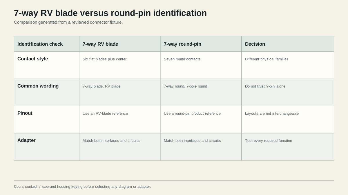
Search results show why names alone fail. “7-way round” can mean a round outer housing with RV blades or seven actual round pins. “7-flat” may mean an RV blade connector, but in other regions “flat” can describe an entirely different layout. “Commercial seven-way” may refer to a heavy-vehicle interface whose circuit scheme is outside this site’s light-trailer RV-blade scope.
Use a controlled naming record:
Seven-contact, RV-blade family, trailer plug, mating face, key at top.
or:
Seven-contact, round-pin family, vehicle socket, rear terminal view, manufacturer and part number recorded.
That sentence contains more useful information than “7-pin plug.” It also gives the next person enough context to interpret a photo or pinout.
Names that require another check
| Listing phrase | What it may mean | Required confirmation |
|---|---|---|
| 7-pin round | Either circular RV-blade housing or seven round contacts | Contact shape photo |
| 7-way blade | Usually RV blade | Key, connector half, and view |
| 7-flat | Sometimes RV blade; region-dependent | Physical layout and market scope |
| 7-pole | Only the number of electrical positions | Contact family and governing documentation |
| RV plug | Often RV blade, but not a specification | Product drawing and terminal labels |
| Commercial plug | Possible round-pin heavy-vehicle family | Exact standard, voltage, and equipment documentation |
Do not use product photos that hide the contact face. A title can be wrong, copied, or optimized around several naming variants. Prefer the manufacturer’s drawing, part number, installation sheet, and a clear photo of both interfaces.
Inspect a listing before ordering
Treat an online listing as incomplete until it answers all of these questions:
- Does the photo show flat blades or round contacts clearly?
- Is the item the vehicle-side receptacle, trailer-side plug, or a matched set?
- Does the manufacturer publish a keyed-interface photo or dimensional drawing?
- Is a wiring or terminal diagram available for the exact part number?
- If it is an adapter, are both connector families named rather than only their contact counts?
- Does the documentation describe circuit mapping, or only physical fit?
- Are voltage and application scope stated for a non-light-trailer system?
Reject a listing whose title, photo, and specification disagree. A product described as “7 round to 7 flat” is especially ambiguous because each word may refer either to the housing or the contact style. Save the exact manufacturer document, not just the marketplace title, with the installation record.
For used equipment, inspect both the outer housing and the replaceable insert. A connector may have been repaired with an insert or cord that no longer matches the original housing documentation. Molded labels on the current insert and traced functions outrank a faded model label on another part.
Connector half is separate from connector family
The vehicle usually provides a socket or receptacle, while the trailer usually carries a plug. Sellers sometimes use “male,” “female,” “plug,” and “socket” inconsistently because blade and socket contact details can be visually confusing. Name the equipment side directly: vehicle side or trailer side. Then name mating face or rear wire-entry face.
The vehicle-side versus trailer-side guide shows why front and rear drawings mirror. This matters after the family is identified; it cannot rescue a diagram from the wrong family.
Understand why pinouts are not interchangeable
Physical mismatch is the obvious problem. Electrical mismatch is the more important hidden problem. Even when an adapter mechanically joins two families, each circuit must be routed to the corresponding function. A one-to-one contact count does not prove one-to-one function placement.
Fit, mapping, and capability are three tests
- Fit: Do the connector and adapter physically mate, key, retain, and seal as designed?
- Mapping: Does each input function reach the intended output contact?
- Capability: Does the tow vehicle actually provide every required source, controller output, ground path, and protected auxiliary circuit?
An adapter may pass the fit test and fail mapping because it targets another convention. It may pass fit and mapping but fail capability because the vehicle lacks a brake-controller output. It may appear correct with a small tester but fail under the trailer’s operating load because a contact or ground path has excessive resistance.
Common scenarios
| Vehicle interface | Trailer interface | First decision | What an adapter cannot prove |
|---|---|---|---|
| RV blade | RV blade | Confirm halves and RV-blade pinout | Active brake, auxiliary, or reverse circuits |
| Round-pin | Round-pin | Identify exact round-pin product/standard | That both ends share the same assignment |
| RV blade | Round-pin | Use a documented family-to-family adapter or rewire plan | Correct circuit mapping and load capability |
| Round-pin | RV blade | Same as above in the opposite direction | That names or colors match functions |
| Any seven-way | 4-way flat | Choose a documented adapter path | Creation of brake, auxiliary, or reverse functions |
| 4-way flat | Any seven-way trailer | Inventory required trailer functions | Electric-brake or auxiliary output from four inputs |
The existing 4-way to 7-way adapter guide explains the last case in detail: an adapter changes the interface but cannot synthesize absent circuits.
Circuit layouts serve different system assumptions
The RV blade combines left stop/turn and right stop/turn on two circuits in the familiar North American light-trailer arrangement. Other seven-contact families may separate functions differently or operate under another standard. This is why translating only the ground and lighting colors is insufficient.
Do not improvise a mapping for brake output, auxiliary power, battery charging, ABS/EBS, or another high-consequence function. Determine system voltage and governing documentation. A connector that looks heavy-duty is not evidence that it can safely carry an unspecified load.
Failure modes caused by family confusion
Family confusion produces more than a plug that will not fit. It can select the wrong tester, move a correct output to the wrong clock position, choose an adapter that passes only lighting, or transfer a combined stop/turn assumption into a system that separates those functions.
| Observed problem | Possible family-related cause | Evidence needed before repair |
|---|---|---|
| Plug almost fits but will not seat | Family mismatch, damaged key, or wrong insert | Clear face photos and exact part drawings |
| Adapter fits but functions are crossed | Adapter mapping or convention differs | Input/output function test and adapter instructions |
| Lighting works but service brakes do not | Brake output is absent or mapped elsewhere | Controller procedure and contact-by-function record |
| Brakes apply unexpectedly | Brake contact receives auxiliary or another active source | Disconnect; trace both sides and adapter |
| One vehicle works, another does not | Different outputs, configuration, or controller | Separate vehicle-side acceptance records |
| Replacement cord colors disagree | Different convention or previous repair | Molded labels, tracing, and function tests |
Do not “correct” the trailer solely because one tow vehicle disagrees. First prove the output mapping of both vehicles. A trailer may be wired for one documented round-pin fleet convention while a new vehicle uses RV blade. The answer could be a dedicated adapter, a standardized fleet re-termination, or retaining separate equipment groups.
Decide between adapter and re-termination
Choose a documented adapter when the connection is occasional, the two product families are positively identified, the adapter explicitly supports both, and every required circuit can be verified. Consider a correctly specified permanent connector change when one trailer must consistently match a known fleet or vehicle interface and the work can follow equipment documentation.
Do not re-terminate merely to make a common plug fit if the original connector serves a documented system that would lose functions. Preserve the original assignment record before removing anything. Label conductors by verified function, not original color, and keep a reversible mapping table.
| Decision question | Adapter favored | Re-termination may be favored | Stop |
|---|---|---|---|
| Use frequency | Occasional cross-family connection | Permanent known pairing | Unknown future equipment |
| Documentation | Adapter mapping is published | Replacement connector diagram is published | No authoritative mapping |
| Circuit support | All required paths supported | All required paths can be correctly rebuilt | Brake/power function unresolved |
| Condition | Both connectors sound | Existing connector damaged or obsolete | Heat, arcing, severe corrosion |
| Verification | Every output can be tested | Full installation can be inspected and tested | No safe controlled test available |
Route to the correct orientation-specific reference
Once the physical family is known, select the next source deliberately.
For an RV blade in the site’s North American scope, use the 7-way RV blade pinout. It provides paired rear views and separates traditional and SAE J2863 wire-color conventions from physical function positions. Use the pinout lookup when you want a bounded selector that refuses unsupported views.
For a round-pin connector, find the exact manufacturer, part number, equipment manual, and applicable standard. Do not use the RV-blade diagram. If the equipment is heavy commercial, agricultural, imported, military, or otherwise outside the light-trailer scope, use documentation for that system and voltage.
Verification sequence after identification
- Disconnect and inspect both interfaces for damage, contamination, altered keys, and readable labels.
- Record connector family, equipment side, viewing face, key orientation, manufacturer, and part number.
- Obtain the exact pinout or adapter mapping from the controlling documentation.
- With the trailer disconnected and vehicle secured, verify vehicle outputs one commanded function at a time.
- Follow the installed brake-controller procedure for brake output rather than assuming a static voltage behavior.
- Verify auxiliary sources, protection, and intended loads from vehicle and product documentation.
- Trace trailer-side conductors to loads and return paths.
- Connect the secured trailer and repeat every required function under operating conditions.
- Stop if any observed function conflicts with the record.
Evidence record
Keep a small handoff table with the vehicle connector, trailer connector, adapter part number, view used, each verified function, test method, intentionally unused contacts, and unresolved items. Photograph molded terminal labels before closing the housings. Store the record with the trailer documentation.
This evidence is especially important when several tow vehicles or trailers share a yard. A connector that worked in one pairing does not prove a different adapter or vehicle supplies the same brake and auxiliary paths.
Build a fleet compatibility matrix
For more than one tow vehicle or trailer, create rows for vehicles and columns for trailers. Each intersection records the tested direct connector or adapter, required functions, date checked, and unresolved limits. Do not mark a whole row compatible because one lighting-only trailer passed.
| Record field | Why it matters |
|---|---|
| Vehicle connector family and part | Distinguishes RV blade from round-pin and replacement inserts |
| Controller and active outputs | Confirms whether electric-brake capability actually exists |
| Trailer connector family and assignment | Preserves the trailer-side convention |
| Adapter manufacturer and part | Makes the mapping reproducible |
| Required function set | Prevents a lighting-only pass from approving a braked trailer |
| Loaded test result | Exposes poor contacts and returns hidden by an unloaded tester |
| Review trigger | Requires recheck after vehicle, plug, cord, adapter, or controller changes |
Standardization can reduce mistakes, but only when performed from a verified inventory. Replacing every connector with the most common-looking type without documenting circuit differences can reproduce the same error across the fleet.
Accept an adapter only after an end-to-end test
Start with a circuit inventory for the trailer, not the adapter package. List required running lights, left and right stop/turn, service brakes, reverse, auxiliary power, and any system outside this light-trailer scope. Mark each as required, intentionally unused, or unresolved.
Test the tow-vehicle interface while the trailer is disconnected. For lighting, command one function at a time. For service brakes, use the brake-controller manufacturer’s procedure. For auxiliary power, document source state, protection, voltage system, and intended load. The result is an input-side record.
Next, compare the adapter’s published input-to-output mapping. A physical family-to-family adapter should identify which contact on the source becomes which function on the destination. If the documentation shows only product photos and connector counts, it is insufficient for high-consequence circuits. Obtain the instruction sheet or choose another product.
Test the adapter output against the input record before attaching the trailer when the product procedure permits. Then connect the secured trailer and repeat the required functions under their normal controlled test conditions. Record any function that the adapter does not carry. Do not label a seven-to-seven adapter “full function” merely because the contact counts match.
Use four acceptance outcomes:
| Outcome | Meaning | Next action |
|---|---|---|
| Pass | Fit, mapping, and required operation agree | Record the tested pairing |
| Limited pass | Documented lighting works; another circuit is intentionally unsupported | Restrict use to the documented trailer task |
| Fail | A required function is absent, crossed, unstable, or overloaded | Disconnect and diagnose from the last passing boundary |
| Blocked | Family, mapping, voltage, controller, or load remains unknown | Obtain documentation or qualified inspection |
Recheck after any vehicle software/configuration change that affects towing outputs, controller replacement, connector repair, adapter replacement, or trailer rewire. The adapter is part of the tested electrical system, not a neutral piece of plastic between two plugs.
Do not let a continuity-only result close the job. Continuity can show that two accessible contacts are connected, but it does not establish contact quality under load, correct controller behavior, adequate ground return, connector retention, weather sealing, or compatibility with every trailer paired to the vehicle. A lamp tester can confirm selected lighting outputs but cannot certify an electric-brake or auxiliary-power circuit. Record which instrument and operating condition supported each result so that a later owner does not treat a limited test as approval of the complete seven-circuit interface. When a function cannot be tested safely with available documentation and equipment, mark it blocked instead of inferring success from the other circuits.
Stop conditions
Do not connect or tow when:
- the contact family remains uncertain;
- an adapter is described only by pin count;
- the connector does not fully seat or retain;
- a pinout lacks connector half or viewing direction;
- ground is missing or unstable;
- brake output appears on an unintended contact;
- auxiliary power, voltage, or protection is undocumented;
- any housing shows heat damage, arcing, displaced contacts, or severe corrosion;
- required lighting or braking fails the controlled test.
The correct answer is sometimes not an adapter. It may be an equipment-specific harness, a properly documented connector replacement, or qualified inspection of a modified system.
Sources
- CURT trailer wiring reference
- Capital One connector and adapter overview
- Lippert trailer wiring guide
Last verified: August 25, 2026.