There is no universal trailer brake gain number. Gain is one controller setting applied to one compatible tow vehicle, trailer, brake system, load, road surface, and set of conditions. The correct starting point, test method, speed, control sequence, and final observation come from the installed controller and vehicle instructions.
Use this page as a worksheet around that product procedure. It helps identify the controls, prove that setup is appropriate, record test conditions, make bounded changes, and recognize when weak, harsh, unequal, intermittent, or uncontrolled braking is a fault instead of a setting problem.
Safety limit: Do not use controller setup to compensate for damaged, unadjusted, incompatible, unequal, intermittently connected, dragging, or otherwise unverified trailer brakes. Complete stationary system checks first. Perform any dynamic test only in the safe location and under the conditions specified by the vehicle, controller, trailer, axle, and brake manufacturers.
Identify the controller and its documented controls
Record the controller make, model, hardware and software version where applicable, installation type, vehicle configuration, brake technology, number of braked wheels, trailer identity, and current manual. Factory-integrated, proportional aftermarket, time-based, wireless, and electric-over-hydraulic-capable controllers can use different logic and terminology.
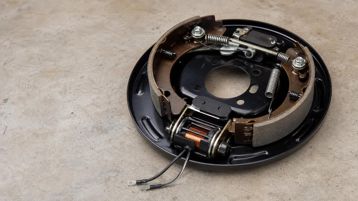
The electric trailer brakes system guide explains the controller, connector, parallel branches, brake assemblies, return, and independent breakaway path. Gain setup assumes those boundaries are already understood and serviceable.
Gain is not every controller control
| Control or state | Typical purpose that must be confirmed | Why it cannot be assumed |
|---|---|---|
| Gain or output | Limits or scales the braking output available under the controller’s logic | Scale, display, and response differ by model |
| Sync, timing, or aggressiveness | Changes when or how rapidly braking develops | Not every controller provides it, and it is not simply another name for gain |
| Boost | Changes initial or proportional response in covered conditions | Levels and recommended use are product-specific |
| Brake type or mode | Selects electric drum, electric-over-hydraulic, or another supported mode | Wrong mode can create unsafe or misleading behavior |
| Trailer profile | Stores settings for a particular trailer or configuration | A stored profile can be wrong after equipment or load changes |
| Manual control | Commands trailer brakes independently under the controller’s design | Static and moving behavior can differ; it is not a universal emergency procedure |
| Connection or fault display | Reports the controller’s interpretation of circuit state | A normal display does not prove every brake or mechanical component |
Tekonsha’s electronic brake-control instructions define output gain and a separate sync control for the covered controller. They also direct periodic adjustment for changes including road conditions, trailer loading, and brake wear. Another controller may use boost, sensitivity, aggressiveness, trailer type, or an integrated vehicle menu instead. Read its definitions before touching a setting.
Confirm controller and brake compatibility
Identify whether the trailer uses electric drum brakes, electric-over-hydraulic actuation, hydraulic surge brakes, or another technology. Confirm that the controller supports it and that the vehicle configuration is enabled as required. Do not infer compatibility from the connector or from a display that turns on.
Capture the exact manuals and their revision dates. If the controller model, brake type, wiring, or current documentation is unknown, stop. A number copied from another driver, trailer, controller, video, or forum is not a safe baseline.
Record current state before adjustment
Write down:
- current gain/output and every other active control;
- selected trailer profile and brake mode;
- controller connection or fault status;
- trailer load and distribution;
- tire, brake, and road condition;
- whether brakes are cold, warm, newly serviced, or recently burnished under their procedure;
- the exact symptom under pedal and manual input where applicable;
- the previous known-good setting and conditions, if documented;
- any recent change to tow vehicle, trailer, controller, wiring, connector, brakes, tires, wheels, axle, battery, or load.
This record prevents the final number from being separated from the conditions that made it valid.
Prepare safe test conditions
Do not begin the dynamic setup merely because the trailer is coupled. Establish that the combined vehicle is safe to test and that the brakes can produce consistent, controlled force.
Pass the readiness gate
Verify under the controlling instructions:
- hitching, coupler, safety equipment, tires, wheels, load, and vehicle ratings are correct;
- controller mounting, power, ground, brake input, configuration, and fault status pass;
- connector assignments, retention, contacts, wiring, and return path pass;
- every applicable brake branch and assembly responds consistently;
- mechanical brake adjustment, wear, contamination, drums, and hardware are serviceable;
- applicable new-brake burnishing or bedding is complete;
- the breakaway system is charged, reset, routed, and separately verified;
- no conductor, connector, controller, magnet, battery, or brake overheats;
- no fuse or breaker repeatedly operates;
- there is no weak, absent, unequal, intermittent, dragging, or no-command braking condition.
The trailer brakes not working guide owns weak or absent application. The brake lockup guide owns uncontrolled, dragging, or excessive application. Repair and verify those faults before returning to setup.
Dexter’s electric-brake manual states that the controller must be set according to its manufacturer and that synchronization can require adjustment for loads and driving conditions. It also warns that proper brake function is critical and directs uncertain operators to professional service.
Record the test environment
Use only the controller or vehicle manufacturer’s specified location, surface, load, direction, speed, brake temperature, traffic clearance, and control sequence. Conditions affect tire grip and observed trailer response. A wet, loose, sloped, crowded, or public-traffic location can invalidate the result and create a hazard.
Record:
- trailer identity, actual current load, and relevant distribution;
- tow vehicle and selected drive or towing mode;
- dry/wet and paved/unpaved surface as applicable;
- grade, temperature, and weather where relevant;
- tire and brake state;
- initial controller settings prescribed by the exact manual;
- whether the test uses manual control, brake pedal, or both;
- target observation in the manufacturer’s words, paraphrased in the service record.
Do not import a test speed or starting gain from this or any general page. Even manuals from the same brand can differ by product.
Establish stop conditions before motion
Abort the test for a warning or fault display, loss of trailer recognition, unexpected application, unequal braking, repeated lockup, poor directional control, smoke, odor, heat, noise, damaged wiring, protection-device operation, or an unsafe test area. Do not continue increasing or decreasing settings to see whether a physical defect disappears.
Adjust output toward smooth firm braking
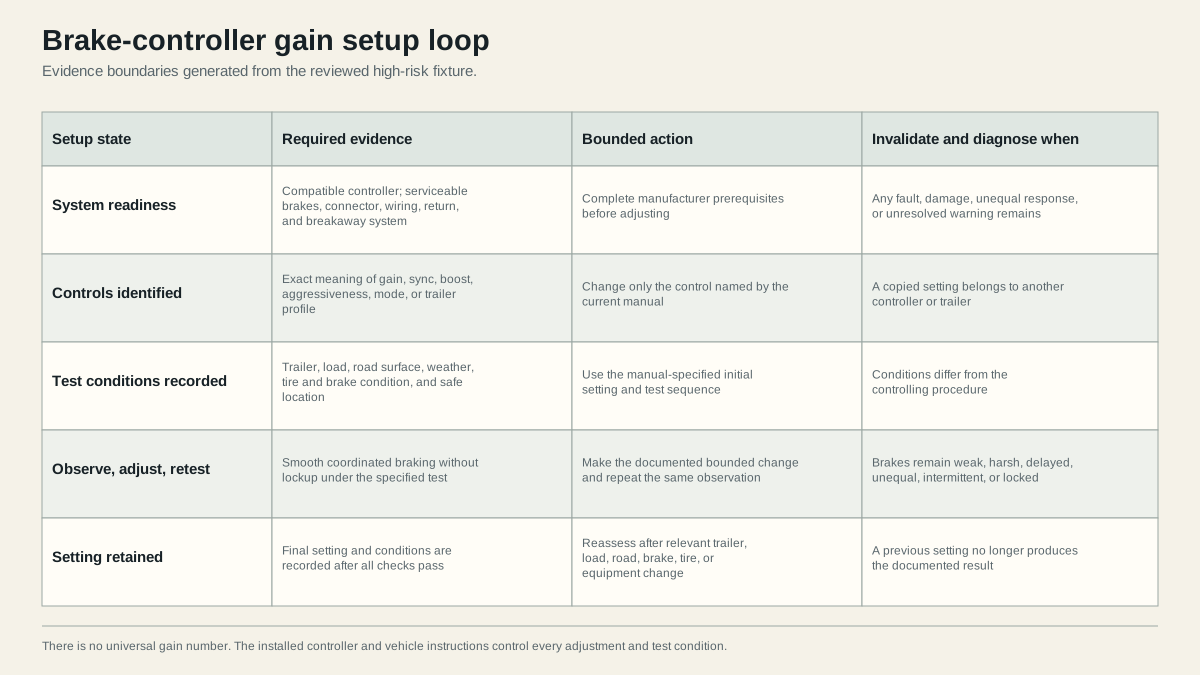
Follow the installed manual step by step. The generic loop is: apply the specified initial setting, make the specified controlled observation, change only the named control by a bounded amount, repeat the same observation, and stop when the product-defined result is achieved or a fault appears.
Change one control at a time
If the manual begins with gain, leave sync, boost, aggressiveness, mode, and profile unchanged unless the procedure explicitly includes them. Changing several controls destroys the evidence that links an observation to an adjustment.
Use a worksheet:
| Trial | Load and conditions | Control changed | Previous value | New value | Command used | Observed result | Pass, continue, or diagnose |
|---|---|---|---|---|---|---|---|
| 1 | Record exact state | Manual-prescribed control | Record | Record | Manual or pedal as specified | Smooth, weak, harsh, lock, unequal, delayed, or fault | Record decision |
| 2 | Must remain comparable | One bounded change | Record | Record | Repeat same specified command | Compare with Trial 1 | Record decision |
The table is deliberately empty of numbers. Its value is preserving conditions and the effect of one change.
Interpret the observation without hiding faults
- Smooth, firm, coordinated braking under the exact procedure: candidate pass. Complete every remaining controller and vehicle verification step.
- Trailer wheels lock or braking is too aggressive only during the valid setup test: make only the reduction or other bounded adjustment specified by the manual, then repeat under the same safe conditions.
- Braking remains weak after the permitted adjustment range or procedure: stop setup. Diagnose controller output, connector, wiring, return, branches, magnets, adjustment, and mechanical condition.
- One wheel, side, or axle differs: stop setup. A global gain cannot repair a local branch or mechanical difference.
- Brakes apply without command or remain applied after release: stop immediately and diagnose controller, connector cross-feed, breakaway path, wiring, or mechanical drag.
- Controller loses connection, reports a fault, or protective equipment operates: stop and follow the exact fault procedure.
Do not use wheel lockup as a universal requirement. Brake type, tires, load, surface, and manufacturer guidance affect whether lockup can or should occur. Tekonsha and Dexter instructions for covered products seek controlled braking without undesirable lockup, but the exact target and method remain product-specific.
Separate manual-control and pedal results
Manual control can test or command trailer braking differently from the brake pedal under a controller’s design. Pedal response can depend on stoplight input, deceleration, vehicle communication, timing logic, or other inputs. A pass with manual control does not automatically clear pedal behavior, and the reverse is also true.
Record both only when the manual requires them. If one input behaves correctly and the other does not, preserve that split and move to the controller or vehicle diagnostic path rather than changing global gain until both appear acceptable.
Finish the product procedure
Some controllers require additional sync, boost, sensitivity, profile, or pedal checks after gain. Perform them in the specified order. Confirm that settings save correctly, the selected trailer profile is active, and no warning appears. Recheck connector retention and brake release after the test.
Recheck after load road or equipment changes
A gain setting is a record tied to conditions, not a permanent specification. Store the final controller value together with tow vehicle, trailer, brake mode, trailer profile, load, surface, brake state, tire state, test date, manual revision, and observed result.
Conditions that invalidate the previous result
Reassess under the current controller and vehicle instructions after a relevant change, including:
- a different trailer or trailer profile;
- a material load or distribution change;
- changed road, weather, grade, or traction conditions when the manual calls for adjustment;
- brake adjustment, repair, replacement, wear, or burnishing;
- tire or wheel change;
- controller replacement, reset, software update, remounting, or configuration change;
- tow-vehicle change or factory tow-system service;
- connector, harness, ground/return, axle, or breakaway repair;
- storage followed by corrosion, battery, brake-surface, or connection concerns;
- any new weak, harsh, locked, delayed, unequal, intermittent, or fault behavior.
Do not assume that heavier always means one fixed increase or that empty always means one fixed decrease. Use the product procedure and observe the complete combination.
Pre-trip confirmation is not a full reset every time
Perform the controller, vehicle, and trailer pre-trip checks specified for the system. Confirm correct profile and mode, connection status, breakaway readiness, connector security, and expected low-speed or stationary response where the manuals require. A full gain setup may not be required on every trip if nothing relevant changed, but a stale setting is not evidence that the current combination passes.
Stop rather than tune around a defect
Keep the trailer out of service when brakes are inadequate, uncontrolled, unequal, intermittent, dragging, overheated, noisy, or inconsistent; when a controller or vehicle fault remains; when the system is incompatible or unidentified; or when the required safe test cannot be completed.
Use qualified service for factory tow-module faults, unknown controller compatibility, brake assembly inspection without correct supports and dust controls, contradictory measurements, repeated protection operation, or any result outside product documentation. A higher gain can increase command, but it cannot repair a restricted connector, damaged wire, faulty return, unequal branch, worn magnet, contaminated lining, incorrect adjustment, or damaged drum.
After any repair, restart at readiness rather than resuming from the old number. The final pass must show normal release, consistent brake response, safe coordinated braking under the documented procedure, breakaway readiness, and no unresolved warning or stop condition.
Sources
- Tekonsha electronic brake-control instructions
- Dexter electric-brake service manual
- etrailer trailer-brake troubleshooting guide
Last verified: August 26, 2026.