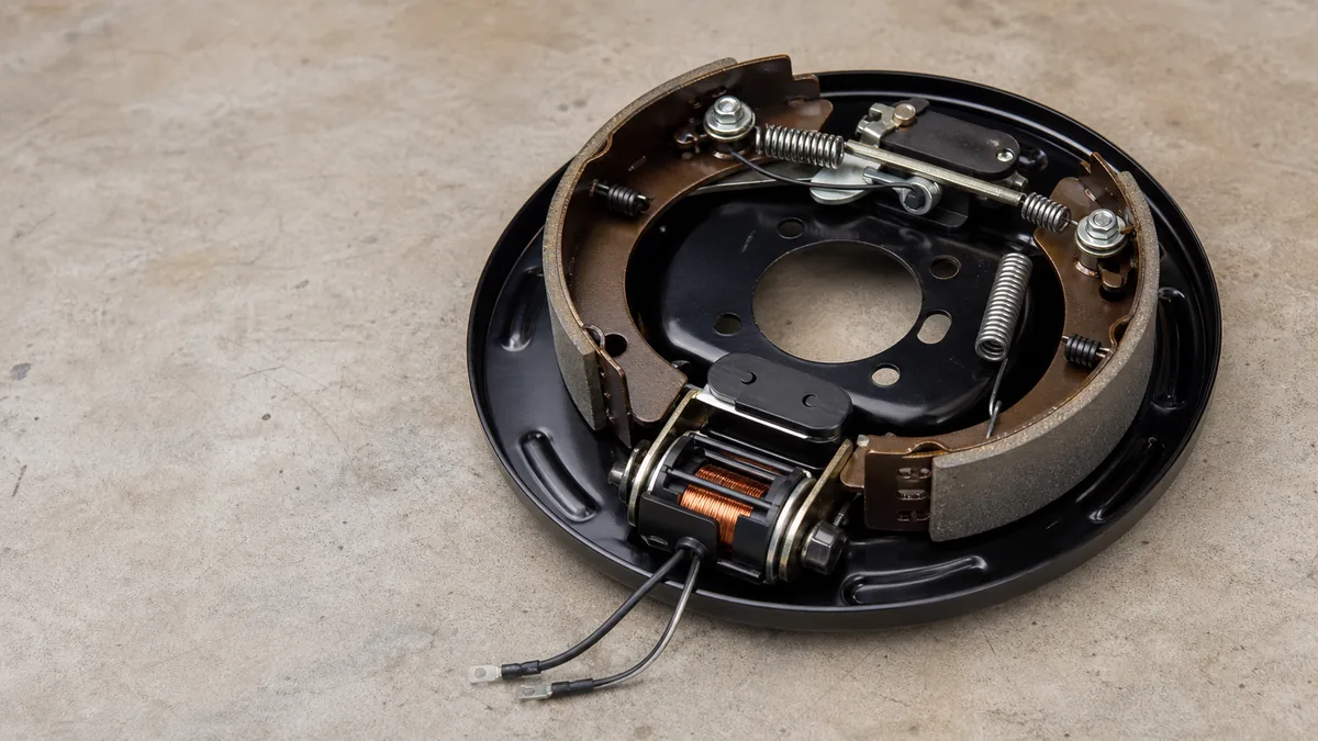
Weak or absent electric trailer braking is not one fault. The controller can lack an input or output, the connector can interrupt the circuit, a main feed or return can be restricted, one parallel branch can differ, magnets can be incompatible or worn, and the drum hardware can be out of adjustment, contaminated, damaged, or seized. The symptom alone cannot identify which layer failed.
If the component boundaries are unfamiliar, start with the electric trailer brakes system guide, then return here with the installed controller and brake information.
The fastest reliable approach is to preserve boundaries. Record what the controller reports, verify the exact controller procedure, test from source toward load, compare like branches, and then hand off to the brake manufacturer’s mechanical inspection. Do not increase gain until the underlying system and setup are known to be serviceable.
Do not tow on an unresolved brake fault. Chock and secure the trailer before stationary checks. Use the vehicle, controller, trailer, axle, and brake-assembly procedures. Do not crawl under or lift a trailer without the specified support equipment and support points. Stop for overheated wiring, smoke, damaged insulation, repeated protection-device operation, a damaged battery, fluid leakage, or any mechanical defect.
This page covers electric service brakes that are weak or do not apply. It does not own unexpected lockup or drag, controller gain setup, breakaway testing, hydraulic surge brakes, or electric-over-hydraulic diagnosis. Those systems and symptoms require their own product-specific procedures.
Record controller status and brake behavior
Begin without changing anything. A useful symptom record distinguishes a source problem from an interface, branch, or mechanical problem before tools touch the circuit.
Record these observations:
- exact tow vehicle, controller model, trailer, axle, and brake assembly;
- trailer loading and whether the symptom appeared after storage, service, rewiring, or a new vehicle;
- connector family and which half and face orientation are being referenced;
- controller display before connection, after connection, with the brake pedal, and with manual control where its manual permits;
- whether no brakes, weak brakes, delayed brakes, or unequal braking affects every wheel or only part of the trailer;
- whether the condition is constant, intermittent, temperature-related, or movement-related;
- current controller settings, but do not adjust them yet;
- status of the breakaway pin, battery, and visible wiring without activating an unidentified procedure.
Translate the controller display using its own manual
Controller messages are product-specific. Tekonsha’s electronic brake-control instructions separate conditions such as no controller power, incorrect ground or supply wiring, a missing stoplight input, and trailer-related output behavior. Another controller can use different codes, connection logic, self-tests, or compatibility rules.
Use this interpretation discipline:
- A controller that is unpowered cannot command the brakes. Verify its documented power, protection, ground, mounting, inputs, and setup before moving rearward.
- A controller that responds to manual control but not the brake pedal suggests a different input boundary from a controller that responds to neither.
- A controller that reports no trailer has not proved that all magnets failed. The unresolved recognition or circuit path can include the controller, vehicle wiring, socket, plug, trailer harness, branches, loads, and return.
- A normal display does not prove that adequate output crosses the connector or reaches every wheel under load.
If the controller is incompatible with the installed brake technology, stop. Do not troubleshoot an electric-over-hydraulic actuator as though it were a set of electric drum magnets. Confirm the controller and actuator compatibility statements first.
Classify the symptom before choosing a test
| Observation | First question | Keep separate from this path |
|---|---|---|
| No brake response and no valid controller activity | Does the exact controller have required power, ground, input, and setup? | Wheel adjustment until source operation is established |
| Controller recognizes trailer but all brakes are absent | Does the documented brake output cross the vehicle socket and connector? | Breakaway activation as a substitute for normal-source testing |
| All brakes respond but feel weak | Does adequate electrical actuation reach the assemblies, and are the brakes mechanically serviceable? | Blindly adding gain |
| One side or axle differs | Where does that branch first diverge from a known comparable branch? | Replacing every magnet |
| Brakes lock, drag, or apply without command | Is the normal or breakaway circuit unintentionally energized, or is hardware dragging? | This no/weak-brake decision path |
| Behavior changes when the plug or harness moves | Which connector, splice, or chafe boundary changes state? | A static parts list |
Dexter’s electric-brake troubleshooting section treats open circuits, short circuits, controller faults, grounds, connections, adjustment, magnets, linings, drums, and broken hardware as distinct possible causes. That source supports a layered diagnosis, not a conclusion that one listed cause explains every trailer.
Test the normal electrical path
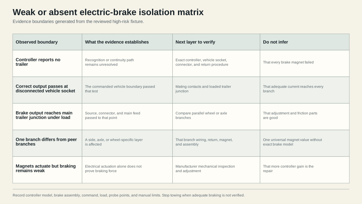
Trace the circuit by function rather than color: controller, vehicle brake-output terminal, mating trailer terminal, main brake feed, distribution point, parallel wheel or axle branches, brake loads, and return. The electric brake wiring diagram shows the conceptual topology.
Before measuring, choose the applicable controller-manufacturer procedure. Some tests use manual control, some use specified display states or dedicated diagnostic steps, and some vehicle modules require scan or service information. Do not short terminals, inject battery power into an unidentified position, or bypass a fuse or breaker.
Establish the tow-vehicle boundary
With the trailer disconnected, identify the vehicle socket orientation and brake-output function from trustworthy documentation. Confirm the controller state and perform its specified output test. A valid result at the disconnected vehicle socket establishes that the vehicle produced the expected command at that boundary during that test. It does not establish loaded performance or clear the trailer.
If the output is missing or wrong, remain on the vehicle side. Check only the items covered by the controller and vehicle procedures: supplies, grounds, brake input, harness, factory tow equipment, protection, connector wiring, mounting, programming, compatibility, and configuration. Do not modify factory wiring from a generic diagram.
If output is correct disconnected but changes when the trailer is connected, inspect the interface and loaded circuit. Restricted contacts, a short, a load problem, a return fault, or protective electronic behavior can exist even though the open connector passed. Record both states.
Cross the connector deliberately
Inspect the vehicle socket and trailer plug for corrosion, heat damage, spread or pushed-back contacts, moisture, loose retention, strain, and damaged cable entry. Verify function position on both halves. A familiar conductor color is supporting information only after the circuit is traced.
Reconnect only when the selected test requires it and the combination is secured. Compare the command on the vehicle side of the interface with the trailer side using an appropriate loaded method. A digital meter can show a plausible value through a high-resistance path when little current flows. Product procedures, a suitable load method, voltage-drop testing, or approved current measurement can reveal faults that an unloaded reading misses.
Do not publish or apply a universal pass value. The correct output pattern, total current range, individual magnet value, and permissible voltage drop depend on the exact controller, number and model of brake assemblies, conductors, connections, command, and test conditions.
Follow the trailer feed and return together
At the trailer junction, identify the incoming brake feed and return. Continue toward each branch, preserving the first point that passes and the first that fails. Inspect tongue flex points, junctions, frame transitions, axle crossings, splices, suspension movement zones, and brake lead entries.
The return is an equal part of the circuit. A feed measurement referenced to an uncertain chassis point can misclassify a return fault as a feed fault. Dexter’s diagram specifies returning trailer brakes through the connector in the covered arrangement. Follow the exact trailer and brake documentation rather than assuming that incidental frame contact is an adequate return.
Useful evidence includes:
- command and controller state;
- trailer connected or disconnected;
- meter or test method and its rating;
- feed and reference points;
- unloaded or loaded condition;
- result and manual limit;
- repeated result after moving only the suspected boundary;
- comparison with a confirmed like branch.
Separate electrical output from brake assembly condition
Once the correct command reaches the main trailer junction under the selected test, compare parallel branches. If one branch differs from another equivalent branch, localize the difference before opening a brake. Inspect its supply conductor, splice, return, brake leads, and physical routing.
Do not compare unlike magnets or assemblies to one universal resistance or current figure. Dexter publishes model- and brake-count-dependent diagnostic information in its manual. Other manufacturers may specify different ranges and methods. Identify the brake size and part information, then use the exact table and measurement conditions.
What a magnet check can and cannot prove
A product-defined magnet electrical test can help identify an open, short, ground fault, incorrect population, or unequal branch. It cannot prove that the magnet face, drum armature surface, actuating lever, shoes, adjustment, lining, drum, springs, and related mechanical parts create adequate braking.
Likewise, hearing a magnet or feeling attraction during a stationary test proves only limited actuation. It does not establish correct force, all-wheel response, mechanical condition, synchronization, or safe stopping performance.
If electrical results at the brake assemblies meet the exact manufacturer procedure but braking remains weak, make a mechanical handoff. Record the electrical tests as passed, then inspect or have a qualified technician inspect the applicable items under the axle and brake manual:
- correct brake assemblies and orientation;
- manual or self-adjusting mechanism condition;
- shoe-to-drum adjustment where applicable;
- lining and magnet wear;
- contamination by grease, oil, or other material;
- scored, grooved, cracked, or out-of-round drum surfaces;
- seized, bent, loose, broken, or incorrectly installed components;
- burnishing or bedding status after applicable new parts;
- axle, bearing, wheel, tire, and loading conditions that affect performance.
Brake dust can be hazardous, particularly with older linings. Dexter warns against creating or breathing dust and against compressed-air or dry-brush cleaning in the covered service procedure. Do not open or clean a brake assembly without the required protective method and product instructions.
Use the first failed boundary, not the loudest symptom
The decision record should end in one of these bounded outcomes:
| Evidence pattern | Localized layer | Correct next action |
|---|---|---|
| Controller fails its own supply, input, setup, or output test | Vehicle or controller | Follow exact controller and vehicle service procedure |
| Vehicle output passes disconnected but fails across the mated interface | Connector or loaded trailer interaction | Inspect contacts, alignment, retention, load, return, and protection behavior |
| Main trailer feed fails after a known passing connector boundary | Main harness or junction | Repair the proven segment with approved materials and routing |
| Main feed passes but one comparable branch differs | Branch, return, magnet, or assembly | Continue only on the differing branch using the exact brake manual |
| Electrical checks pass at every assembly but braking is weak | Mechanical setup, wear, contamination, drums, loading, or compatibility | Perform manufacturer mechanical inspection and setup |
| Evidence is inconsistent or the system cannot be identified | Unresolved | Stop and obtain qualified diagnosis |
Changing several parts at once removes this evidence. Make one supported repair, then repeat the same test before moving to the next layer.
Confirm braking performance or stop towing
A repair is not complete when the controller code disappears or a meter changes. Reinspect the physical work, protect every conductor, restore junction covers and strain relief, verify connector retention, and perform the full controller and brake-manufacturer post-service procedure.
At minimum, the final record should establish:
- controller powers, recognizes the installed application, and responds correctly to each required input;
- documented output crosses the connector without an intermittent or overheated contact;
- the main trailer feed and return pass under the required condition;
- every applicable parallel branch and brake assembly produces a consistent product-defined result;
- mechanical adjustment and component condition meet the exact brake manual;
- normal service braking is synchronized according to the controller, vehicle, trailer, and brake instructions;
- the breakaway system separately passes its own product procedure;
- no protection device opens and no conductor, connector, battery, magnet, or assembly overheats.
Do not use an uncontrolled public-road test to discover whether the trailer has brakes. If a manufacturer procedure includes a dynamic setup or confirmation, use its specified safe location, loading, speed, sequence, and conditions only after stationary checks pass. Keep people and traffic clear. A trailer that cannot demonstrate adequate braking under the controlling procedure remains out of service.
Conditions that require a stop
Stop before towing if any required brake remains weak, absent, unequal, intermittent, locked, or dragging. Also stop when the system type is unknown, a controller fault remains, measurements conflict with the manual, the breakaway system is not ready, wiring is damaged or hot, a connector is loose or burned, a fuse or breaker repeats, or mechanical inspection is incomplete.
Seek qualified service when diagnosis requires lifting without rated supports, opening brake assemblies without the correct tools and dust controls, repairing factory tow modules, resolving controller compatibility, machining drums, replacing structural or running-gear parts, or evaluating a result outside published limits.
Federal commercial-vehicle rules, state rules, and inspection requirements can impose additional obligations. They do not replace the product checks. Confirm the laws that apply to the actual trailer, tow vehicle, weight, and use.
Sources
- Dexter electric-brake service and troubleshooting manual
- Tekonsha electronic brake-control instructions
- etrailer trailer-brake troubleshooting guide
Last verified: August 26, 2026.