Choose a symptom, then enter an observed test result
The tool returns the next diagnostic boundary. It does not declare a failed part from a symptom.
Stop for heat damage, arcing, repeated fuse/protection operation, unstable braking, or any required lamp that cannot be verified. Use the exact vehicle, converter, connector, lamp, and trailer documentation.
This diagnostic tree returns a fault class and next test, not a guaranteed failed part. Select the observed function pattern, record the disconnected tow-vehicle output, and describe what happens under the relevant load. The tool preserves the first unresolved electrical boundary and sends you to the canonical procedure that owns it.
The tree is intended for common North American light-trailer exterior-lighting systems. It does not determine connector assignments, vehicle fuse locations, legal lamp requirements, conductor size, voltage limits, or product compatibility. Identify the connector family and use the exact vehicle, harness, connector, lamp, and trailer documentation. Do not tow with required lamps inoperative.
Select the failed and working functions
Begin with an observation another person could reproduce. Choose none only when no exterior lighting function operates. Choose running only when tail, marker, or clearance lamps fail while stop/turn behavior remains substantially functional. Choose stop-turn for one- or two-sided visible service-brake or turn-lamp failures. Choose interaction when lamps are dim, flicker, cross-flash, or change as another command is applied.
Before using the selector, complete a short function record:
| Command | Left rear | Right rear | Tail/marker group | Notes |
|---|---|---|---|---|
| Running lamps | normal/off/dim | normal/off/dim | normal/off/dim | Note groups, not just “all” |
| Left turn | pulse/off/wrong | unintended response | unintended response | Record timing and brightness change |
| Right turn | unintended response | pulse/off/wrong | unintended response | Compare with left |
| Service brake | steady/off/wrong | steady/off/wrong | unintended response | This concerns visible lamps |
| Combined command | record | record | record | Use the combination that recreates the complaint |
Do not combine contradictory symptoms merely to force a result. If one lamp is completely off and several others cross-act only under load, the system may contain more than one fault. Start with the pattern that is repeatable and safety-critical, preserve all other observations, and re-run the tree after each verified repair.
The tree does not use wire color as an input. Brown, green, yellow, white, blue, black, and red are common clues in various connector contexts, but installed assignments can differ. It also does not ask whether “the ground looks good,” because visual appearance is not a loaded electrical test.
What the tool refuses to infer
- Working brake lamps do not prove electric wheel brakes work.
- Working stop/turn lamps do not prove the running contact or all shared returns are good.
- A correct unloaded output does not prove the connector can carry the operating load.
- Dim lamps do not prove a ground fault without feed/return measurements.
- An opened fuse does not identify the short, overload, module, or damaged segment.
- A physical adapter does not create a missing vehicle output.
If the connector family or view is uncertain, identify it with the trailer lighting wiring guide and vehicle-side versus trailer-side orientation guide before entering test results.
Run the vehicle-side versus trailer-side split
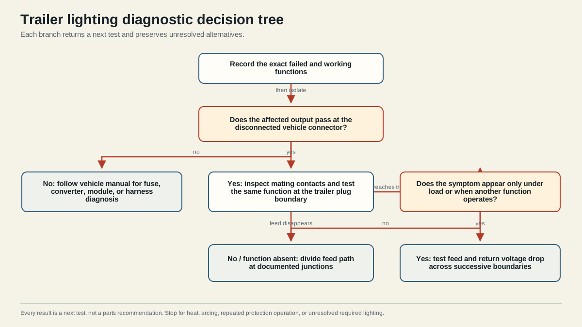
The disconnected vehicle connector is the first useful split because it prevents trailer conditions from hiding the source output. Secure the vehicle and trailer, disconnect the plug, orient the vehicle-side connector using molded labels and reliable documentation, and command only the function being tested. Follow the vehicle and test-equipment instructions and avoid bridging adjacent contacts.
Record one of these evidence states:
- Pass: the intended output appears at the correct disconnected contact under the commanded function.
- Fail: the intended output is absent, on the wrong contact, or otherwise incorrect with the trailer disconnected.
- Pass unloaded, fail loaded: the disconnected output appears correct, but connected operation collapses, opens protection, becomes unstable, or causes interaction.
- Not tested: there is no valid boundary evidence yet. The tool should refuse a component-level conclusion.
A failed disconnected result keeps the first unresolved fault on the tow-vehicle side. The exact vehicle may use dedicated trailer-light fuses, an electronic towing module, an aftermarket converter, configuration logic, or some combination. Consult the installed documentation; never replace protection with a larger rating or bypass a module output.
A passing disconnected result moves the first unresolved boundary to the mating connector or trailer. It does not guarantee that the output will carry load. Inspect contact fit and retention, then trace the relevant trailer branch. When behavior changes only connected, measure feed and return voltage drop while the symptom is present.
Why the third input matters
The loaded-behavior selection prevents a correct-looking unloaded reading from becoming an automatic trailer-lamp verdict. “Stable” means the commanded output and intended lamps remain consistent under the actual test condition. “Collapses” covers a source or contact that loses performance when connected. “Protection opens” is a short/overload or protection-response branch, not permission to keep resetting. “Interaction” covers dimming, flicker, or unintended lamp response when load or commands change.
Follow branch-specific tests
The interactive result returns a branch owner and one next action. Use the result as a test plan, then record what happened. Do not skip ahead to the most familiar replacement.
| Returned class | What is established | Canonical next procedure |
|---|---|---|
| Vehicle-side output missing | The required disconnected output has not passed | Vehicle/harness documentation and source-output diagnosis |
| All-light trailer-side path | Vehicle source passed; a shared trailer boundary remains | General lights-not-working procedure |
| Running branch | Stop/turn evidence narrows the failure to the tail/marker family | Running-lights isolation |
| Stop/turn branch | Side and command symmetry define the next output/branch test | Stop and turn lamp procedure |
| Loaded feed/return path | Behavior changes under current or combined functions | Dim/flicker loaded test |
| Protection operation | A cause remains before another reset or replacement | Segment the de-energized circuit using exact protection instructions |
| Insufficient evidence | Inputs are missing or conflict | Reproduce functions and test the disconnected connector |
For a trailer-side branch, move from upstream to downstream: trailer plug termination, main harness, first junction, side or group branch, lamp input, and return network. At each accessible boundary, compare the input with the output under the failing command. The first change is more useful than a list of possible parts.
Worked branch: running lamps off, stop and turn lamps working
Select the running-only symptom only after confirming the left and right stop/turn commands. If the disconnected vehicle running output fails, the tree returns vehicle-side ownership; consult the exact vehicle or harness instructions for protection, module, configuration, and output testing. If it passes, inspect the running contact and trace the trailer tail branch. All tail and marker lamps off prioritize the plug, main feed, first junction, and a return boundary shared under the larger running-light load. One group off moves the next test downstream to that group’s junction.
If the vehicle output appears correct disconnected but protection opens or voltage collapses connected, select that loaded behavior instead of forcing a simple trailer-side pass. De-energize and segment the branch. The tool never suggests a larger fuse, because protection operation identifies an unresolved cause, not an insufficient consumable.
Worked branch: one stop/turn side fails
Record left turn, right turn, and service brake separately. One side failing for both stop and turn selects a side-specific path, but the disconnected output still decides ownership. A failed vehicle output keeps work upstream; a passing output moves to the same-side mating contact, conductor, lamp input, and return. Do not use electric brake-controller output as a substitute test; visible stop lamps and wheel-brake magnets are separate circuits.
When turn works but stop fails on both sides, the lamp paths have demonstrated some function, while the vehicle’s service-brake-to-trailer conversion remains unresolved. Test both service-brake outputs. If they pass unloaded but fail connected, use the loaded branch. This retains more evidence than replacing both lamps or one assumed converter.
Worked branch: dimming or cross-action
Select interaction when applying one command changes another lamp’s brightness or timing. Confirm the relevant disconnected outputs first. If the interaction already exists there, stay with the vehicle or converter. If the outputs are clean disconnected, recreate the exact combined load and measure the complete feed and return paths. The result does not automatically label the ground; crossed assignments and feed-side loss remain alternatives until the measurement boundary is proved.
Use the returned dim/flicker owner for the actual loaded procedure. Record physical probe points and the installed equipment’s allowable limits. An unloaded continuity beep or a voltage reading against an unrelated chassis point does not satisfy this branch.
For interaction symptoms, trace the complete return. The return can include a local lamp wire or designed frame connection, intermediate frame bonds, harness return, trailer-plug termination, mating contact, vehicle-socket termination, and vehicle return network. Use the ground troubleshooting guide to test individual boundaries under load. Do not rely on the hitch ball as the intended electrical return.
For protection operation, preserve whether the symptom occurs with the trailer disconnected, connected but commands off, or under one specific command. De-energize before opening junctions. Inspect pinched conductors, wet or contaminated connectors, heat damage, and branch points. Isolate only documented accessible segments, restore the specified protection, and test one change at a time. Never upsize or bridge a fuse.
Tool limitations and safety
The tree does not calculate circuit capacity and does not know the installed current, conductor length, connector condition, or protection strategy. It intentionally contains no universal voltage-drop, resistance, current, fuse, or wire-size values. Use the exact equipment specifications and a qualified technician when measurements, energized work, or vehicle module diagnosis exceed your tools or experience.
Stop immediately for smoke, arcing, hot or melted connectors, exposed conductors, repeated protection operation, unidentified modifications, or any required lamp that cannot be restored and verified. Secure the trailer and keep clear of moving vehicle and coupler parts. A limitations notice does not substitute for evidence.
Verify the repaired lighting system
Once a measurement identifies a boundary, de-energize and repair it using the connector, terminal, splice, sealing, support, and strain-relief instructions. Repair one verified fault at a time so the result remains attributable. A temporary jumper or moved wire may be diagnostic evidence, but it is not a permanent repair unless it meets every applicable electrical and mechanical requirement.
Repeat the command that originally failed, then run the complete lighting matrix: running lamps, left turn, right turn, service brake, hazards, and applicable reverse or auxiliary lighting. Combine running lamps with each stop/turn command because shared resistance may appear only at higher load. Observe every installed lamp for intended brightness and timing, no cross-action, stable connector behavior, and no abnormal heating.
Record:
- symptom selection and all working functions;
- connector family, half, and view;
- disconnected vehicle-output result;
- loaded-behavior result;
- returned fault class and next test;
- first failed physical boundary;
- repair performed and controlling documentation;
- complete final function results.
If the returned branch does not explain the measurement, do not force it. Preserve the finding, return to the last proven boundary, and select the updated observation. More than one fault can exist. If three targeted repair cycles fail, mark the item blocked and seek qualified help rather than continuing random substitutions.
The three-cycle rule applies to evidence-based repairs, not three arbitrary part replacements. A cycle is: state the hypothesis, name the boundary and supporting observation, make one bounded correction, and repeat the original plus full verification tests. If the result contradicts the hypothesis, restore any reversible test setup, preserve the finding, and update the branch. This keeps the tree useful even when the installed system has undocumented changes or multiple simultaneous faults.
For team or shop use, save the tool inputs with the inspection record. Include date, tow vehicle, connector family and view, adapter or converter identity, disconnected result, loaded state, returned owner, measurements, repair, and final matrix. The JSON fixture can change in a future version, so the recorded observations matter more than a screenshot of the result alone.
The acceptance condition is not “the original lamp came on.” Every required installed function must operate correctly alone and in relevant combinations, protection must remain intact, and the connector and repaired path must remain mechanically and electrically stable. Until then, do not tow.
Sources
- CURT trailer wiring reference
- etrailer lighting diagnostic
- NHTSA FMVSS No. 108 interpretation
- Peterson/TMC trailer lighting diagnosis and repair
Last verified: August 26, 2026.