
A trailer lighting system is easiest to understand as a set of functions and complete current paths, not a bundle of colors. The tow vehicle creates a command, the vehicle connector presents an output, the trailer connector accepts it, the harness distributes it to one or more lamps, and the current returns to its source. A fault at any boundary can make the final lamp fail even when every wire appears to have a familiar color.
This guide owns the system overview. It does not replace a connector-specific pinout, a vehicle manual, lamp-installation instructions, or a symptom-specific diagnostic. Use it to name the functions, understand what can be shared, and choose the correct detailed procedure. For safety, do not tow with required lamps inoperative or with an unresolved short, overheated terminal, damaged insulation, or repeatedly opening protection device.
Separate lamp function from wire color
Start by writing down what the trailer must do rather than what colors you see. On a common North American light-trailer arrangement, the basic electrical functions include a return path, tail/running illumination, left stop/turn, and right stop/turn. Other trailers may add reverse lamps, a separate auxiliary circuit, or circuits unrelated to exterior lighting. The connector family determines how many independent positions are available; it does not prove which positions are actually wired on a particular vehicle and trailer.
| Function | Driver command or condition | What to observe | What it does not prove |
|---|---|---|---|
| Tail/running | Parking or headlamps on | Tail, marker, clearance, and applicable identification or license lamps | That every lamp is required on every trailer |
| Left stop/turn | Left turn, then service brake | Left combined lamp responds to both applicable commands | That the electric wheel-brake circuit works |
| Right stop/turn | Right turn, then service brake | Right combined lamp responds to both applicable commands | That vehicle and trailer colors match |
| Reverse | Reverse selected under the vehicle’s safe test procedure | Reverse output or other documented fifth/seventh function | That an adapter can create the signal |
| Return/ground | Every powered test | Stable path back to the source while the load operates | That a continuity beep proves loaded performance |
Wire colors are useful identifiers only after the installed mapping has been verified. CURT’s connector reference explicitly warns that illustrated colors may not match the installed system. Previous repairs, replacement cords, wishbone harnesses, regional conventions, vehicle converters, and proprietary connectors can all break a color-only assumption. Position is also ambiguous until you state the connector family, connector half, and whether the view shows the mating face or the rear wire-entry side.
Before disconnecting or moving a conductor, record:
- connector family and contact count;
- tow-vehicle side or trailer side;
- mating-face or rear-view orientation;
- each commanded function measured at the disconnected vehicle connector;
- each conductor’s traced destination on the trailer;
- the exact vehicle, harness, lamp, or trailer documentation that controls limits.
This inventory prevents two common errors. The first is mirroring a correct pinout because its viewpoint was lost. The second is making a trailer “match the chart” without first proving that the tow vehicle follows the assumed assignment. Use the connector types guide when the housing itself is uncertain.
Lighting function is not the same as legal scope
The existence of a tail circuit does not tell you how many marker, clearance, identification, or license lamps a specific trailer requires. NHTSA material treats lighting by equipment function and applies some requirements according to vehicle dimensions, placement, and application. State or local operating rules may also matter. This page therefore does not publish a universal lamp-count checklist. Identify the trailer, dimensions, use, jurisdiction, and controlling requirements before an installation or modification.
Trace basic stop turn and tail circuits
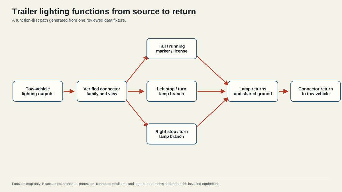
Read the diagram from source to return. A lighting command begins in the tow vehicle. Depending on the vehicle, factory towing equipment or an approved converter/module may create trailer outputs. Those outputs reach the vehicle connector, cross the mating contacts, enter the trailer harness, split at branch junctions, energize the intended lamps, and return through a dedicated conductor, frame bonds where designed, connector return contact, and vehicle return network.
The left and right stop/turn feeds are usually independent on common four- and seven-contact light-trailer connections. Each combined lamp can receive a pulsing turn command and a steady service-brake command on the same side-specific feed. That architecture is why one failed side and two failed sides carry different diagnostic information. It is also why the blue electric-brake output on a seven-way must not be confused with red stop-lamp illumination: wheel-brake controller output is a separate circuit and task.
The tail/running feed commonly branches to multiple lamps. A single open near the connector can extinguish every running lamp. An open after a branch can affect only the downstream group. A short can open a vehicle or harness protection device, but simply replacing the device does not remove the short. A working left or right stop/turn lamp shows that some source, connector, lamp, and return behavior remains, yet it does not prove every shared contact or return boundary is healthy under a different combined load.
The return path completes every circuit. Treat it as a conductor network, not a vague bolt called “the ground.” A lamp may return through its own wire to a junction; a designed frame bond may then carry current to the connector return; the vehicle connector and vehicle wiring complete the path. Paint, corrosion, loose hardware, damaged crimping, contamination, or undersupported terminals can add resistance at any boundary. Peterson/TMC’s diagnostic material emphasizes termination integrity, environmental protection, systematic isolation, repair, and verification rather than symptom-only replacement.
Use the disconnected connector as the first boundary
When diagnosing, disconnect the trailer and test the tow-vehicle output under the vehicle and test-equipment instructions. Command one function at a time. A correct output at the proper contact places the first unresolved fault on the trailer side. A missing or incorrect output keeps the fault on the vehicle side, where fuse locations, towing modules, converter logic, configuration, and protection are vehicle-specific.
An unloaded tester identifies an output but may not prove current-carrying performance. If the output is correct disconnected and collapses or behaves incorrectly with the trailer operating, inspect the mating contacts and measure the affected feed and return paths under load. Do not use a random wire swap as a diagnostic shortcut; it destroys the evidence boundary and can place an unrelated circuit on a lamp or return terminal.
Recognize dimension-dependent lighting scope
A connector diagram answers a narrow question: which contact is intended for which circuit in a stated family and view. It cannot establish the complete exterior-lighting design for every trailer. Required equipment can depend on trailer width, length, rating, build date, configuration, and jurisdiction. Lamp visibility, color, location, orientation, certification, reflector requirements, and installation method may be controlled independently of the connector assignment.
Use this division of responsibility:
| Decision | Generic guide can establish | Controlling evidence still needed |
|---|---|---|
| Circuit purpose | Function names and common architecture | Installed connector labels and measured mapping |
| Lamp inventory | Functional categories to investigate | Trailer/application requirements and manufacturer documentation |
| Conductor route | Source-to-load-to-return boundaries | Physical inspection and trailer wiring documentation |
| Protection | Need for an appropriately protected circuit | Vehicle/harness/product fuse and conductor specifications |
| Voltage loss | Need to test while current flows | Equipment-specific limits and measurement procedure |
| Repair acceptance | Every affected and adjacent function must pass | Vehicle, lamp, connector, and trailer instructions |
For a new or rewired trailer, inventory the required lamps first, then group them by independently commanded function. Select a connector with enough documented circuits, design the branches and return path, and choose conductors, protection, connectors, and environmental sealing from the calculated load and exact product requirements. A four-contact housing cannot provide independent reverse, auxiliary-power, or electric-brake functions merely because an adapter presents a seven-contact socket.
For an existing trailer, preserve the installed configuration until it is documented. Photograph connector orientation, label each function, and trace both feed and return. If a conductor disappears into an inaccessible harness, divide the path using accessible junctions rather than guessing. If modifications conflict with documentation, stop and resolve the conflict before energizing the circuit.
Safety and limitations
Secure the tow vehicle and trailer before testing, keep clear of traffic and moving coupler parts, and follow the vehicle procedure for brake, turn, and reverse commands. Do not probe in a way that spreads contacts or creates a short. Disconnect power before opening junctions unless a controlled energized measurement is specifically required and you are equipped to perform it safely. Heat, melted housings, repeated fuse operation, smoke, exposed conductors, or unidentified modules are stop conditions.
Choose an installation or troubleshooting path
Use the narrowest page that owns the task. This prevents a broad article from repeating incomplete versions of every procedure.
| Your task or symptom | Canonical owner | First evidence to collect |
|---|---|---|
| Identify a connector and available functions | Trailer connector types | Physical family, contact count, side, and view |
| Map a common four-contact connector | 4-pin trailer wiring diagram | Four disconnected vehicle outputs |
| Map an RV-style seven-way | 7-pin trailer wiring diagram | Connector family and face orientation |
| No trailer lamps work or pattern is unclear | Trailer lights not working | Failed and working functions |
| Only tail, marker, or running lamps fail | Running lights not working | Disconnected running-output result |
| Stop or turn lamps fail | Brake lights and turn signals not working | Left/right and stop/turn symptom matrix |
| Lamps are dim, flicker, or cross-act | Dim or flickering trailer lights | Controlled combined-load symptom |
| You need a guided next test | Trailer light diagnostic tree | Symptom, vehicle-output result, loaded behavior |
| Return path is suspected | Trailer ground troubleshooting | Loaded voltage-drop measurements across boundaries |
| Replace a damaged basic utility-trailer harness | How to rewire utility trailer lights | Required-lamp inventory, 4-way topology, routing, terminations, and final tests |
After any repair or installation, repeat a complete functional check. Test tail/running lamps, left turn, right turn, service-brake lamps, hazard behavior where applicable, reverse or auxiliary lighting if installed, and any other documented exterior-lighting function. Observe individual and combined commands because a shared high-resistance point may appear only when current demand rises. Confirm the connector remains fully seated, the cord has clearance and strain relief, repaired junctions are supported and sealed as specified, and no conductor or terminal heats abnormally.
Record pass/fail results by function rather than writing “lights fixed.” Include the tow vehicle used, adapter or harness identification, connector family and view, measured boundary, repair performed, and unresolved application questions. A different vehicle can expose a different converter, output assignment, or protection scheme even when the physical connector mates.
For a transferable handoff, add a simple sketch of the actual branch points and label any conductor whose installed color differs from the reference convention. Note whether each observation was made disconnected, connected without load, or connected with the intended lamps operating. Those states are not interchangeable. This small record prevents a later owner from undoing a correct nonstandard installation merely to make colors match a generic chart, and it gives the next diagnostic a proven starting boundary.
The system passes only when every required installed lamp responds correctly to its command, no unintended lamp responds, operation remains stable under realistic combined load, protection stays intact, and the repair meets the controlling equipment instructions. Anything less is a diagnostic checkpoint, not permission to tow.
Sources
- NHTSA FMVSS No. 108 interpretation
- SAE J1239 scope
- CURT trailer wiring reference
- Peterson/TMC trailer lighting diagnosis and repair
Last verified: August 26, 2026.