Trailer stop lamps and electric wheel brakes are not the same circuit. On common North American light-trailer wiring, the visible left and right stop lamps share their respective feeds with the left and right turn signals. Electric brake magnets receive a separate controller output on trailers equipped for them. If the red lamps fail when the service brake is pressed, changing brake-controller gain or probing the electric-brake output is the wrong first task.
Use the failed and working commands to narrow the path. One side failing for both stop and turn points toward a side-specific vehicle output, connector contact, conductor, lamp, or return boundary. Both sides failing requires independent left and right output tests before blaming one universal fuse or converter. Stop towing until required signaling works consistently.
Separate stop lamps from electric wheel brakes
Use precise names when recording the complaint:
- Service-brake lamps are the visible red lamps commanded by the brake pedal.
- Turn-signal lamps flash on the commanded side.
- Hazard lamps flash both sides through vehicle-specific logic.
- Electric wheel brakes apply braking force at the trailer wheels from a brake-controller output and, separately, an emergency breakaway system where fitted.
The word “brake” creates misleading search results because a page about brake lights may drift into controller output, magnet resistance, or breakaway wiring. Those topics have different sources, risks, and tests. If the trailer wheel brakes fail while the visible lamps work, use the electric trailer brake wiring diagram. This page stays with exterior stop and turn lamps.
On a typical four-way flat and RV-style seven-way blade system, the left stop/turn and right stop/turn functions occupy separate connector positions. The tow vehicle may generate these combined outputs directly or through factory towing electronics or an approved converter. A converter can translate a vehicle with separate stop and turn lamps into the combined trailer outputs. Its design, protection, and diagnostic behavior are vehicle- and product-specific.
Record the following before unplugging anything:
| Command | Left trailer lamp | Right trailer lamp | Running/marker lamps | Electric wheel-brake behavior |
|---|---|---|---|---|
| Left turn | flashing/off/wrong | off/wrong | unchanged/wrong | not inferred |
| Right turn | off/wrong | flashing/off/wrong | unchanged/wrong | not inferred |
| Service brake | steady/off/wrong | steady/off/wrong | unchanged/wrong | not inferred from lamps |
| Hazards | flashing/off/wrong | flashing/off/wrong | unchanged/wrong | not inferred |
| Running lamps | dim/normal/off | dim/normal/off | normal/off | separate task |
Do not use hazards alone to declare both sides good. Vehicle logic may command hazards through a different path than a single turn or service-brake input. Test the actual commands involved in the complaint.
Compare left and right symptoms
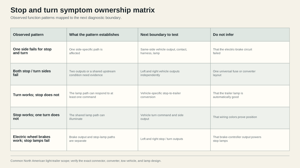
The matrix is a prioritization aid, not a diagnosis. It helps you preserve what the symptom proves:
One side fails for both stop and turn
The stop and turn commands share the same side-specific trailer feed after the vehicle has created the combined output. When both commands fail on one side while the other side works, test that failed side’s disconnected vehicle output first. If it passes, continue through the same-side mating contact, trailer conductor, lamp terminal, and return boundary. Do not replace both lamps merely because both commands are missing; they may be one physical lamp on one shared feed.
Both sides fail for stop and turn
This may indicate two missing outputs or a shared upstream condition, but the pattern does not identify one universal fuse, converter, module, or ground. Test left and right vehicle outputs independently. If both are missing, consult the exact tow-vehicle and harness instructions. If both are correct disconnected, look for connector seating, return-path behavior under load, or trailer faults affecting both branches.
Turn works but stop does not
A lamp responding to its turn command shows that it can illuminate on that side-specific feed, but it does not prove the vehicle receives and converts the service-brake command correctly. Compare left and right service-brake outputs at the disconnected connector. A vehicle-specific stop-input, towing module, converter, or configuration issue may affect both without changing turn commands. Do not infer that the trailer is automatically fault-free; test the connected condition if the outputs pass unloaded.
Stop works but one turn does not
This pattern establishes that the shared trailer lamp path can illuminate under the service-brake command. The missing single-turn command remains upstream until tested at the connector. Check the vehicle turn indication and disconnected side output. If the correct pulse appears there but not at the lamp when connected, trace the mating contact and side branch under the failed command.
Electric wheel brakes work but stop lamps fail
That result reinforces the separation: controller output can reach brake magnets while the left/right lighting outputs fail. Do not move the brake-output conductor onto a stop/turn position or use controller behavior as proof of lamp feeds. Identify the connector family and each function independently.
Test stop-turn outputs at the vehicle connector
Disconnect the trailer and secure the vehicle. Identify the vehicle-side connector and the stated diagram view. A mating face and rear wire-entry view can be mirrored; use molded labels and the exact harness documentation. Then command left turn, right turn, service brake, and hazards one at a time while observing the intended contacts.
| Disconnected result | Boundary decision | Next action |
|---|---|---|
| One side output absent for both its commands | Vehicle side unresolved | Check vehicle-specific protection, module/converter, harness, input, and configuration |
| Both side outputs absent | Vehicle side unresolved | Verify test reference, then inspect each output and shared upstream inputs using documentation |
| Outputs correct for all commands | Trailer side unresolved | Inspect mating contacts and trace failed side feed and return |
| Output correct unloaded but collapses connected | Load-dependent boundary unresolved | Test connector, feed, and return voltage drop while the symptom occurs |
| Unintended contact responds | Assignment or vehicle conversion problem | Stop and verify connector view, wiring, and module instructions |
Do not publish or rely on a generic vehicle fuse number. A dedicated towing fuse, electronic protection, or converter can exist in different locations and behave differently. Replacing a fuse with a larger value or bypassing a module protection output risks conductor and component damage.
If the vehicle outputs pass, inspect contact retention and contamination at both halves. Follow the failed side conductor from the plug to its first junction and lamp. Verify signal at the input and output of each accessible boundary under the failing command. A correct signal before a crimp and missing signal after it makes that termination actionable. A missing signal before the junction keeps the fault upstream.
At the lamp, distinguish feed from return. A correct potential measured against an unrelated reference may coexist with a poor installed return. Test across the operating lamp circuit and measure individual feed or return boundaries as the equipment procedure requires. The ground troubleshooting guide explains why unloaded continuity can pass when an operating load still fails.
Example evidence paths
Suppose the left turn and left stop command both fail, the right side works, and the disconnected left output also fails. The trailer-side lamp and conductor have not been cleared, but they are not the first unresolved boundary; the next work belongs to the vehicle’s left trailer-light output and its documented upstream inputs. In contrast, if the disconnected left output passes both commands, the first unresolved boundary moves to the mating contact and left trailer branch. That distinction prevents two systems from being opened at once.
Now suppose both turn commands work but neither side illuminates with the service brake. Because both side feeds can operate, replacing both trailer lamps is weakly supported. Test both disconnected service-brake outputs. If they fail together, investigate the vehicle-specific brake-input-to-trailer conversion path. If they pass, recreate the connected brake command and test the interface under load. The trailer can still contain a shared loaded return fault even though each turn works alone.
A third pattern, one lamp responding to the opposite command, requires orientation and assignment verification before continuity hunting. Confirm the vehicle connector family and face, identify each disconnected output, then trace the trailer plug from the same declared view. A mirrored diagram or crossed repair can create a clean but wrong command; a resistance fault more often changes intensity or creates weaker interaction. Measurements, not the pattern alone, decide.
Combined-lamp details
Some lamp units have separate low-intensity tail and high-intensity stop/turn functions; others implement these electronically. A working tail element does not prove the stop/turn input, and a working stop/turn function does not prove the tail input. Use the lamp’s documented terminals and test procedure. Do not assume an LED unit can be repaired internally or that a visible incandescent filament proves the circuit.
When one command lights both sides or makes another lamp pulse, move to a loaded shared-return and crossed-circuit investigation. A poor return can force current through unintended lamp paths, while crossed conductors can directly apply the wrong feed. The symptom alone does not distinguish them.
Verify combined functions after repair
Repair one verified fault at a time. Use connectors, terminals, seals, support, and strain relief appropriate to the installed product and environment. Do not leave a temporary probe puncture, unsupported jumper, twisted splice, or bypassed protection as the repair. If heat damage extends into a housing or conductor, follow product replacement instructions rather than cleaning only the visible contact.
After repair, repeat this acceptance sequence:
- left turn alone;
- right turn alone;
- service brake with both sides steady;
- hazards;
- tail/running lamps alone;
- tail/running plus left turn;
- tail/running plus right turn;
- tail/running plus service brake;
- other installed lighting commands under their documented procedure.
Watch for brightness changes, delayed response, cross-flashing, or a connector that moves when the cord is flexed normally. Combined commands matter because they increase current through shared return and connector boundaries. A repair that passes a single turn test but fails with running lamps on is incomplete.
Record the original matrix, disconnected vehicle outputs, first failed boundary, repair, and complete final results. If any required stop or turn function remains failed, protection operates, the connector heats, commands cross-act, or the vehicle-specific converter/protection cannot be verified, stop. A working electric brake controller does not make failed stop lamps safe, and working stop lamps do not validate electric wheel brakes.
Include the identity of the tow vehicle and any converter or adapter in that record. The same trailer can pass behind one vehicle and fail behind another because their towing outputs, monitoring, protection, or conversion differ. A second vehicle can be useful comparative evidence, but it is not a substitute for measuring the original vehicle; never rewire the trailer solely to match an unverified comparison vehicle.
For a guided selection of the next boundary, use the trailer light diagnostic tree. Its output is a fault class and next test, not a replacement recommendation.
Sources
- CURT trailer wiring reference
- etrailer lighting diagnostic
- NHTSA FMVSS No. 108 interpretation
- Peterson/TMC trailer lighting diagnosis and repair
Last verified: August 26, 2026.