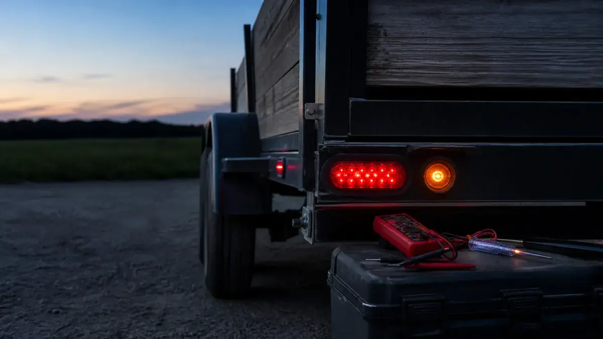
If the trailer’s brake and turn lamps work but its tail, marker, or clearance lamps do not, begin with the running-light output, not a universal parts list. The working stop/turn functions show that at least some connector contacts, lamp circuits, and return behavior can operate. They do not prove the running contact, shared connector return, every branch ground, or the tow vehicle’s running-light output is good under load.
The fastest safe split is a disconnected test at the tow-vehicle connector. If the correct running output is absent there, stay on the vehicle side. If it is present, preserve that result and divide the trailer path into connector, main feed, branch junctions, lamps, and returns. Do not tow at night or in conditions that require the failed lighting, and stop if insulation, terminals, or protection devices show heat damage.
Confirm the exact working and failed functions
Reproduce the complaint with the trailer and tow vehicle stationary and secured. Do not begin by saying “the lights don’t work.” Command each function separately and record the result at every installed lamp.
| Command | Left rear | Right rear | Side/clearance/marker | What the pattern suggests |
|---|---|---|---|---|
| Parking/headlamps | record | record | record | Defines the running/tail family failure |
| Left turn | record | should remain off unless designed otherwise | normally unchanged | Tests the left combined feed |
| Right turn | normally unchanged | record | normally unchanged | Tests the right combined feed |
| Service brake | record | record | normally unchanged | Tests both combined stop feeds |
| Hazard | record | record | normally unchanged | Useful confirmation, not a substitute for separate commands |
This page owns the specific pattern in which the running/tail/marker family is failed or incomplete while stop and turn commands substantially work. If no functions work, several unrelated patterns exist, or the connector family is unknown, start with the general trailer-lights diagnostic. If the lamps glow dimly, flicker, or affect one another rather than simply staying off, use the loaded dim/flicker procedure.
Interpret working lamps carefully
Working left and right stop/turn lamps are useful evidence. They show that the vehicle can create those two commands, the corresponding contacts can mate, the side feeds reach their lamps, and some return path exists at that load. They do not eliminate all return faults. A high-resistance connector return or frame bond can behave acceptably with one lamp and fail when several tail and marker lamps operate together.
Likewise, one working marker lamp proves only its local branch and return at that moment. It does not prove the main tail feed continues beyond that point. Use the physical order of junctions, not lamp position alone; a visually distant lamp may branch electrically near the connector.
Inspect before energizing further. Look for a partially seated plug, green or white contamination, backed-out contacts, a pinched cord, unsupported splices, damaged insulation, wet junctions, loose lamp mounts where the design uses a local return, and repairs that change color mid-run. Color is a tracing aid, not proof. Brown is common for tail/running on some diagrams, but the installed function must be measured.
Test running-light output at the vehicle connector
Disconnect the trailer. Identify the connector family, vehicle half, and view. A front/mating-face diagram and a rear wire-entry diagram can appear mirrored, so confirm molded labels or the exact harness documentation before selecting a contact. The vehicle-side versus trailer-side guide explains this orientation boundary.
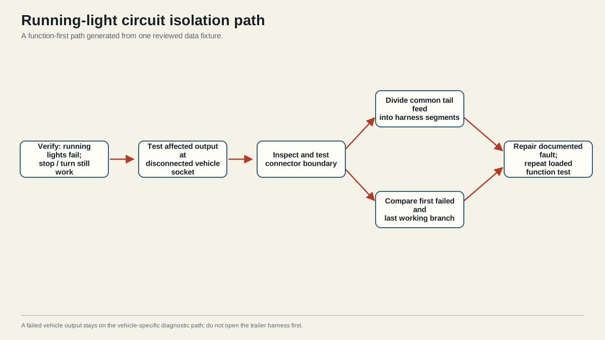
Follow the vehicle and test-equipment instructions. Establish the meter or test-light reference correctly, command the parking/headlamps, and test the intended running-light contact. Compare it with known working left and right outputs so that a poor test reference is less likely to masquerade as a missing circuit.
There are three useful outcomes:
- No running output at the disconnected vehicle connector: keep the investigation on the tow vehicle. Consult its manual for towing-light protection, module, converter, configuration, and harness locations. Do not assume the trailer caused the failure, and do not install a larger fuse.
- Correct running output present: the first unresolved boundary is the mating connector or trailer side. Avoid changing vehicle components.
- Output appears unloaded but fails when connected: suspect an inability to carry the operating load, excessive drop at a source or contact, or protection reacting to a trailer fault. This is not a clean vehicle-side pass.
Vehicle implementations vary. Some use a dedicated trailer fuse, some use an electronic towing module, and some use an approved converter to create combined stop/turn outputs. A generic article cannot identify a universal fuse number, rating, or reset method. Use the exact vehicle and installed harness documentation. Repeated protection operation is evidence; preserve it and locate the cause.
Trace the trailer running-light branch
With a verified source output, inspect the trailer plug and cord first. Confirm the running contact is retained, clean, and connected to the traced tail feed. Then follow the conductor to the first junction. Draw the actual branch tree as you find it; do not assume the visible left and right sides are fed independently.
Use the failure extent to select the next boundary:
| Observed trailer result | Highest-value next check | Why |
|---|---|---|
| Every running/marker lamp is off | Trailer plug contact, main feed, first junction, shared return under load | A boundary common to all loads is more likely than simultaneous lamp failures |
| One physical side or group is off | Junction feeding that group and its return arrangement | The main source reached at least one other branch |
| One lamp is off | Local feed terminal, lamp connection, lamp unit, and local return | Upstream branch operation narrows the fault |
| Lamps work until another function is commanded | Feed and return voltage drop under combined load | A shared resistive boundary may pass a light load |
| Protection opens immediately or repeatedly | De-energized inspection and segmented isolation for a short or overload | Replacing protection cannot remove the fault |
At an accessible junction, verify the commanded signal on the incoming side and then on each outgoing branch. The first boundary with a correct input and missing output is actionable. De-energize before opening, cleaning, reterminating, or moving conductors. Follow connector and splice instructions so that the repair restores retention, strain relief, support, and environmental sealing.
Test the return as a complete path. If the lamp has a dedicated return wire, follow it to the return junction. If the design intentionally uses the frame, inspect both the lamp-to-frame and frame-to-harness bonds. Clean metal at one bolt is not proof that every other bond and connector contact supports current. For load-dependent symptoms, use the ground troubleshooting method and measure across individual return boundaries while the affected lamps operate.
Avoid false fixes
A jumper that makes a lamp illuminate can help isolate a boundary when used under a controlled procedure, but it is not automatically a permanent repair. It may bypass protection, use inadequate conductor support, or conceal a damaged original path. Similarly, replacing every lamp can temporarily disturb a corroded connector and create the impression that the new lamp solved the fault. Reproduce the original test after each single repair.
LED lamps can draw differently from incandescent units and may interact with vehicle monitoring or converters. That does not justify adding a resistor or changing a module without product documentation. First prove source, feed, load, and return behavior. Route confirmed LED-specific behavior to a dedicated procedure instead of mixing it into a generic tail-circuit diagnosis.
Find the cause before replacing a fuse again
An open circuit and an opening protection device are different problems. An open prevents current from reaching the load; a short or excessive load can cause protection to operate. If a fuse or electronic protection opens, do not repeatedly reset it, increase its rating, or bridge it. Disconnect the trailer and observe whether the vehicle output returns according to the manufacturer’s procedure. That result helps distinguish a trailer-side fault from a vehicle-side issue but does not identify the exact damaged segment.
With power removed, inspect the running branch where it passes sharp edges, hinges, tilt points, suspension areas, removable gates, lamp housings, and wet junctions. Divide the branch by disconnecting only documented, accessible sections. Restore the specified protection and test after each isolated segment. The segment whose connection recreates the fault contains the unresolved load, conductor, connector, or return issue. Never leave required lamps disconnected as the final repair.
After correcting one verified fault, repeat the complete test matrix, not only the running lamps. Confirm left turn, right turn, service brake, tail/running, marker/clearance, and any documented reverse or auxiliary lighting. Observe combined operation, connector fit, cord clearance, strain relief, and repaired-junction temperature. The pass condition is stable intended illumination, no unintended cross-action, and intact protection under the installed operating load.
Document the connector family and view, tow vehicle, adapter, failed function, disconnected output result, first failed trailer boundary, repair, and final all-function result. If a required lamp remains failed, the connector heats, a fuse or module continues to protect the circuit, or the exact product limits cannot be verified, stop. The system is not ready for towing merely because one test lamp illuminates.
Sources
- CURT trailer wiring reference
- etrailer lighting diagnostic
- NHTSA FMVSS No. 108 interpretation
- Peterson/TMC trailer lighting diagnosis and repair
Last verified: August 26, 2026.