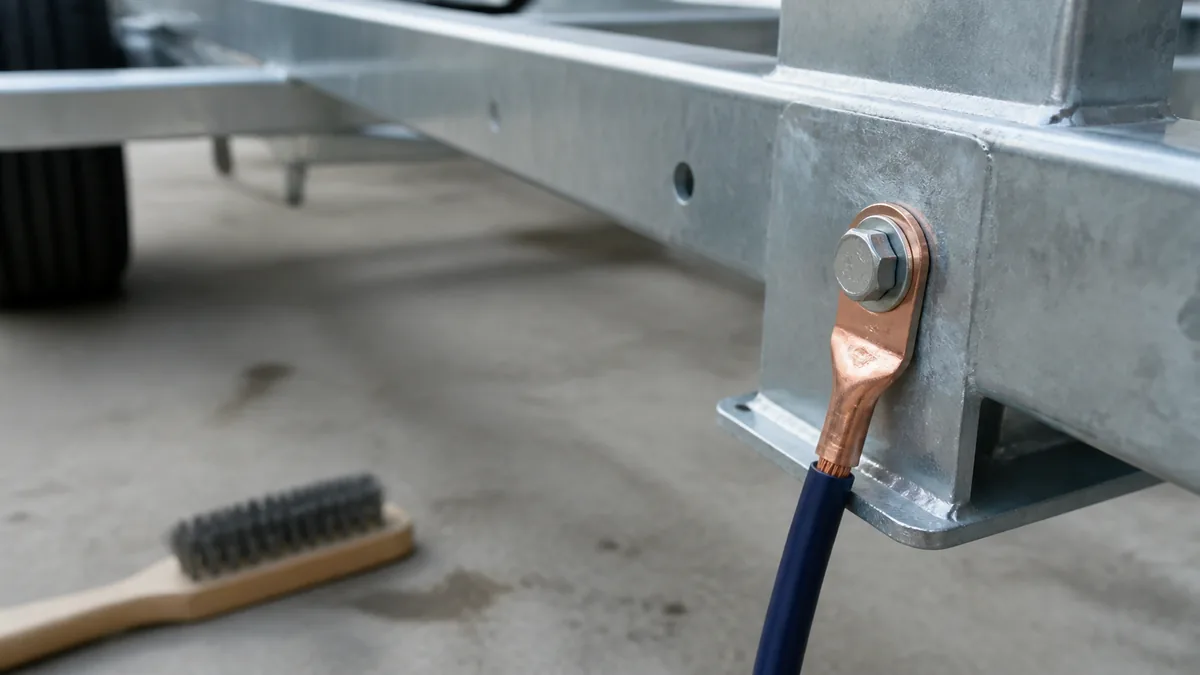
A trailer ground is the complete return route from a load back to the electrical source. The route may include a lamp lead, frame bond, main trailer ground conductor, connector contacts, vehicle wiring, and battery negative. Any high-resistance boundary can affect every load that shares it.
Trace the complete current-return path
Choose one failed load and trace both sides of its circuit. On the return side, identify the load terminal, local splice or frame bond, main ground conductor, trailer plug, vehicle socket, and tow-vehicle negative path. Do not assume the hitch ball is the intended electrical return.
Record every removable connector, splice, fastener, and frame transition. Those are test boundaries. If the fault affects electric brakes, follow the axle and controller manuals because current demand and product checks differ from lighting.
Include moving and dissimilar frame sections
Tilt beds, folding tongues, hinges, bolted subframes, painted or powder-coated members, and aluminum structures can interrupt a frame-based return even when the main tongue bond looks clean. Treat each transition as an electrical boundary until a dedicated conductor or a loaded test proves otherwise.
For a lamp grounded through its mounting hardware, the return may pass through the lamp base, fastener, frame coating, several frame joints, the main frame bond, and the connector. A two-wire lamp with a dedicated return still depends on every splice and connector contact between the lamp and source. Draw the actual path before deciding where “the ground” is.
Match common symptoms to ground-path failures
Dim lamps, flicker as the trailer moves, several functions failing together, or one lamp changing when another function is commanded can be consistent with a shared return restriction. They are not proof. A supply-side restriction, damaged converter, incorrect assignment, or multiple faults can look similar.
First confirm that the correct supply signal reaches the load. Then test the return. This avoids repairing a frame bond when the missing signal is actually upstream.
Use symptoms to choose a test, not declare a cause
| Observed symptom | Ground-related mechanism worth testing | Competing explanation to keep open |
|---|---|---|
| All lamps dim | Shared return restriction affects several loads | Weak supply, connector feed loss, or converter problem |
| Lamps change when brakes or turn signals operate | Current seeks an unintended return through another lamp circuit | Crossed conductors or damaged converter |
| One lamp flickers with vibration | Local terminal, mounting ground, or splice changes resistance | Broken supply conductor or loose lamp assembly |
| Lights work until running lamps are turned on | Added load exposes a weak shared connection | Overloaded or damaged supply-side equipment |
| One trailer section fails after a hinge or tilt point | Frame continuity is interrupted across that boundary | Harness damage at the moving joint |
| Lighting works but brakes are weak | Higher-current brake return may be restricted | Controller, feed, magnet, adjustment, or mechanical fault |
A symptom can rank likely test locations, but it cannot prove the failed part. Preserve alternate causes until measurements isolate a boundary.
Test the return path under load
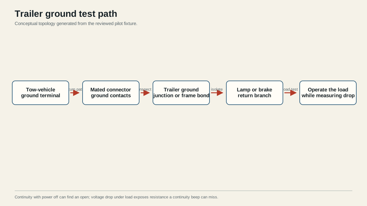
Operate the affected load and measure voltage across each return boundary, moving from the load toward the source. A sound connection should not consume a meaningful share of circuit voltage. The first boundary with an abnormal reading identifies where the return is being lost.
Fluke’s automotive troubleshooting guidance emphasizes that voltage-drop testing is performed with current flowing. An ohmmeter or continuity beep uses very little current and can miss a connection that fails when the circuit is loaded.
Use product documentation to determine acceptable results and test setup. Do not invent a universal threshold for all trailer loads, conductor lengths, brake systems, and instruments.
Measure across one boundary at a time
Voltage drop is measured between two points on the same operating path while current flows. Place one lead before a suspected connection and the other after it, operate the affected load, and observe the voltage consumed by that boundary. Move methodically toward the source. The boundary that accounts for abnormal loss is more actionable than a resistance reading across the entire disconnected trailer.
Useful boundaries include:
- Lamp return terminal to its local ground point.
- Local ground point to the main frame or return junction.
- Frame transition or dedicated return splice to the tongue ground.
- Trailer plug ground contact to vehicle socket ground contact while mated.
- Vehicle socket ground path toward the source negative, following vehicle instructions.
Use fused test leads and safe back-probing methods appropriate to the circuit. Never let a temporary jumper become the permanent repair, and do not bypass a protected return or manufacturer-required connection.
A continuity beep with power off can identify a complete open. It does not load the path the way several lamps or brake magnets do. That explains why a connector may “test good” for continuity and still fail in service.
Repair and protect the verified connection
Disconnect power as required by the installed equipment. Repair only the boundary proven faulty: remove corrosion, restore clean conductive contact, replace damaged terminals or conductors, and tighten hardware to the product specification. Apply environmental protection that does not insulate the intended metal-to-metal contact.
When frame return is unreliable by design, a dedicated return conductor may provide a more controlled path, but its routing, size, terminals, protection, and connection points still need to match the loads and equipment documentation. Do not add a small jumper to a brake or auxiliary return based only on a lighting example.
Document the before and after readings at the same operating load. Also photograph or label the repaired boundary, especially when it is hidden behind a lamp, junction box, folding tongue, or battery enclosure. That makes recurrence easier to isolate without repeating every test.
Reconnect, reproduce the original load, repeat the same measurement, and use the trailer-light diagnostic path to test related lighting circuits that share the return. For a broader source, protection, load, and return classification, continue to the trailer power and grounding guide. Stop before towing if the connection heats, the reading remains abnormal, the failure is intermittent, or any required lighting or brake function remains unreliable.
Sources
- Fluke automotive voltage-drop guidance
- CURT trailer wiring reference
- Dexter electric-brake service manual
Last verified: August 25, 2026.