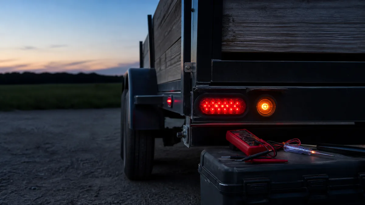
Start by finding where a known command disappears. Do not begin with a new lamp, converter, or harness. Record the failed functions, disconnect the trailer, test the tow-vehicle connector, and only then move into the trailer circuit.
Record which lighting functions fail
Test running lamps, left turn, right turn, and brake lamps. Record whether the fault affects one lamp, one side, one function on both sides, or every lamp. Also note dimming, flicker, or another lamp glowing when a function is commanded.
- One dead function on both sides points toward its vehicle feed, connector terminal, or shared conductor.
- Several unrelated lamps failing together points toward a shared supply or return path.
- One dead lamp with the same function working elsewhere points toward that branch, socket, lamp, or local ground.
- Backfeeding, dimming, or cross-glow often justifies a focused ground-path test. If the symptom began with an LED retrofit, also use the LED-specific compatibility workflow before adding a load device.
Turn the symptom into a circuit hypothesis
| Pattern | First boundary to test | Why it is useful |
|---|---|---|
| No trailer lamps work | Vehicle connector ground and commanded outputs | Separates a shared source/return problem from the entire trailer harness |
| Running lamps fail on both sides | Vehicle running-lamp output, then trailer running branch | Both sides commonly share that circuit |
| One stop/turn side fails | Matching vehicle output, connector contact, then that side’s branch | The opposite side provides a comparison circuit |
| Both stop lamps fail but turns work | Command service brakes at the disconnected vehicle connector | Tests how the vehicle or converter combines the brake input |
| Lamps are dim or change with another command | Supply and return voltage drop under load | Added current can expose a restricted shared boundary |
| Failure changes when the plug or tongue moves | Connector retention, chafe points, hinges, and splices | Movement is evidence of an intermittent boundary |
Record the tow vehicle, connector type, trailer, exact commands, and whether the trailer was connected. “Lights do not work” is too broad to preserve a useful test history.
Split the tow-vehicle side from the trailer side
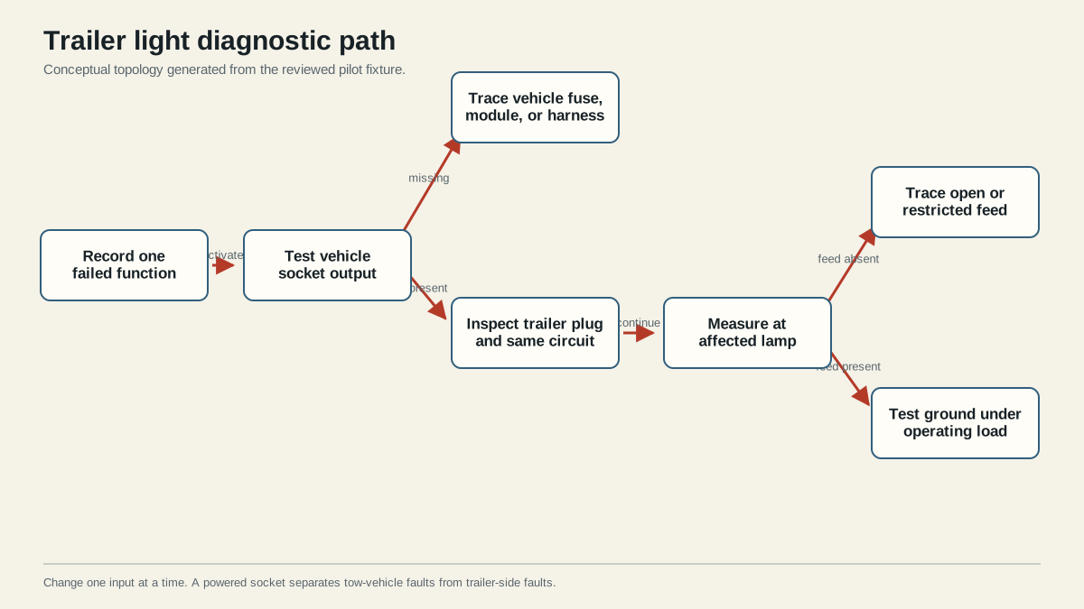
Disconnect the trailer. Establish a known-good tester ground and command one function at a time at the vehicle connector. Use the correct connector orientation and pinout. If the output is missing there, follow the vehicle or converter documentation rather than altering the trailer.
If the output is correct at the disconnected connector, inspect both mating halves for corrosion, looseness, damage, or pushed-back terminals. Optronics’ lighting troubleshooting instructions likewise start at the vehicle connector before moving through the trailer circuit.
Interpret the first split correctly
- Output missing at the disconnected vehicle connector: stay on the vehicle side. Check the applicable vehicle fuses, factory tow package, converter, module, harness, ground, and connector using their documentation.
- Output correct when disconnected but wrong when connected: inspect connector fit and test the circuit under load. A trailer short, overload, or restricted connection may pull the output down, and protected vehicle equipment may shut an output off.
- Output correct through the mated connector: move into the trailer harness and keep following the same named function.
- Tester result depends on where its ground lead is placed: the reference ground is part of the diagnosis. Establish a known-good point before declaring the feed absent.
Do not apply power from a loose battery lead to an unidentified terminal. A wrong injection point can damage vehicle electronics, energize an unintended circuit, or bypass protection.
Follow the failed circuit toward the load
Reconnect only when necessary for a loaded check and prevent the trailer from moving. Follow the affected conductor from plug to junction, through each accessible connection, and toward the first failed load. Compare the signal before and after each boundary. Inspect for chafe, pinching, poor splices, water entry, and loose lamp connections.
Test the return path as part of the circuit. A meter can show nominal voltage with almost no load while a restricted connection fails when lamps draw current. A temporary test lead may help prove a return-path fault, but it is not a permanent repair.
Find the first boundary where the command changes
For a dead left stop/turn lamp, for example, compare the same command at the vehicle socket, trailer plug, first junction, branch splice, and lamp feed. If the signal is correct before a splice and absent after it, the fault lies at that boundary or the segment immediately following it. If the feed reaches the lamp, measure the return path while the lamp is commanded on.
Change one variable at a time. Replacing a lamp, cleaning several grounds, and resplicing the connector before retesting destroys the evidence that identifies the cause. A targeted repair is also easier to verify and less likely to introduce a second fault.
Inspect common physical failure zones while tracing:
- cable entry at the trailer plug;
- tongue junction boxes and exposed splices;
- folding or tilt-tongue transitions;
- points where wire crosses sharp frame edges;
- axle and suspension movement areas;
- lamp mounting holes and local ground fasteners;
- water-exposed connectors and housings.
Visual damage is supporting evidence. The electrical test still determines whether that location explains the failed function.
Confirm the repair and required lamps before towing
After repairing the verified fault, retest running, marker, clearance, stop, and turn functions that apply to the trailer. Wiggle the connector and harness only while stationary to check for intermittent behavior. Confirm both sides remain stable and no unrelated lamp glows.
Use the same symptom record for the final test. Reproduce every command that failed, then test the other required functions to catch disturbed wiring or shared-circuit effects. Where the repair addressed a high-resistance connection, compare the loaded measurement before and after the repair.
Do not call the repair complete because a lamp glows in daylight. Confirm correct function, side, brightness consistency, stability, and interaction with other commands. Secure covers, strain relief, loom, and junction boxes before the road check.
NHTSA’s FMVSS No. 108 interpretation is useful for federal lighting scope, but registration, use, and inspection obligations can also depend on trailer and jurisdiction. Stop before towing when a required lamp remains failed, intermittent, or incorrectly assigned.
Sources
Last verified: August 25, 2026.