Dim, flickering, or cross-acting trailer lights often indicate that current cannot travel cleanly through the operating circuit. A shared return fault is common, but the symptom alone does not prove it. Feed-side corrosion, a loose terminal, a damaged conductor, a failing connector, a vehicle converter problem, or crossed circuits can produce overlapping behavior.
The decisive difference is load. A meter may show source voltage through a nearly open corroded connection when almost no current flows. A continuity test may beep through a path that cannot support several lamps. Fluke’s automotive guidance describes voltage-drop testing as a powered, current-flowing test; Peterson/TMC likewise frames trailer-lighting diagnosis as verification, system checks, isolation, repair, and final confirmation. Reproduce the fault, then measure the complete feed and return path while it is present.
Reproduce the symptom with controlled function combinations
Secure the vehicle and trailer in a ventilated, controlled location. Inspect first for exposed conductors, melted housings, smoke, repeated protection operation, or a connector too hot to handle safely. Those are stop conditions, not invitations to continue an energized test.
Record lamp behavior under one command at a time, then under the combinations that caused the complaint:
| Test state | Left stop/turn | Right stop/turn | Tail/marker group | Diagnostic value |
|---|---|---|---|---|
| Running lamps only | brightness/stability | brightness/stability | brightness/stability | Establishes the base tail load |
| Left turn only | pulse quality | unintended action | unintended action | Isolates left feed and shared return behavior |
| Right turn only | unintended action | pulse quality | unintended action | Isolates right feed and shared return behavior |
| Service brake only | steady level | steady level | unintended action | Loads both stop/turn branches |
| Running plus left turn | record changes | record changes | record changes | Adds shared current and exposes interaction |
| Running plus right turn | record changes | record changes | record changes | Compares side symmetry |
| Running plus service brake | record changes | record changes | record changes | Creates a higher combined lighting load |
Use words that another person can reproduce: “left tail lamp becomes dim only when the right turn signal flashes” is better than “lights weird.” Video can help document timing, but a video is not a measurement. Note whether moving the plug or cord changes the symptom without repeatedly flexing damaged wiring.
The first command that changes another function is especially valuable. If running lamps are stable alone but both dim when the service brake is applied, look for a boundary shared by those loads. If only one lamp flickers regardless of other commands, begin with its local feed, lamp connection, and return. If the wrong lamp illuminates at full intensity with a command, crossed assignments may be more plausible than voltage loss; verify the connector mapping before assuming ground.
Working functions do not clear the entire return path. A shared contact can carry one small load yet develop excessive loss when several lamps operate. Preserve the exact combined condition for the measurements that follow.
Inspect shared connector and return points
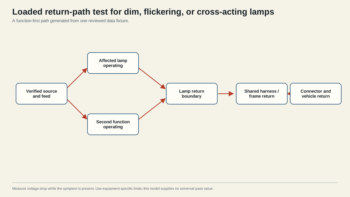
Trace the physical current path before placing probes. On the feed side, it may include the vehicle towing module or converter, vehicle harness, socket termination, mating contacts, trailer plug termination, main harness, branch junction, lamp connector, and lamp electronics or filament. On the return side, it may include a lamp return wire or designed lamp-to-frame bond, frame sections and bonds, return junction, trailer cord, connector contact, and vehicle return network.
Inspect each accessible boundary for:
- contamination, moisture, corrosion, or loss of terminal plating;
- partially seated or backed-out contacts;
- loose crimping, fasteners, lamp mounts, or frame bonds;
- paint, coating, rust, or sealant between designed conductive surfaces;
- pinched, abraded, stretched, unsupported, or heat-damaged conductors;
- unsupported splices and missing strain relief;
- repairs that rely on trailer-ball contact as the normal return;
- incompatible terminals or housings that fit physically but do not retain properly.
Do not conclude that a shiny ground bolt is good. Current may encounter resistance in the crimp attached to it, the frame joint beyond it, the connector return contact, or the vehicle-side termination. The trailer ground troubleshooting guide treats ground as the full return network.
Also verify the source boundary. Disconnect the trailer and confirm that the intended vehicle outputs respond correctly. If the interaction appears at the vehicle socket with the trailer disconnected, keep the fault on the vehicle side and use vehicle-specific documentation. If the outputs are correct disconnected but the behavior appears connected, the mating connector, trailer load, and return network remain unresolved.
Separate resistance from crossed circuits
A resistive shared return often makes lamp brightness change with total load and can create weak or alternating glow through unintended paths. A crossed feed may make the wrong lamp follow a command more directly. These are patterns, not verdicts. Map the disconnected vehicle outputs and trace trailer conductor destinations before moving any wire. Then use loaded measurements to prove where potential is being lost.
Measure voltage drop under load
Voltage drop is measured across a section of an operating circuit. It is not the same as measuring source voltage from a contact to an arbitrary chassis point. Follow the meter, vehicle, and equipment instructions; select the proper function and range; keep probes from shorting adjacent contacts; and avoid piercing insulation unless an approved repair procedure addresses the resulting opening.
Use a bounded sequence:
- Recreate the exact command combination that makes the lamp dim, flicker, or cross-act.
- Verify the tow-vehicle source and command remain stable.
- Measure across the entire feed path to the affected operating lamp.
- Measure across the entire return path from the lamp return boundary back to the source return.
- Divide whichever side shows unacceptable loss into smaller boundaries: connector, termination, conductor segment, junction, frame bond, or lamp connection.
- Continue until the first boundary accounts for the loss under the same load.
Use the installed vehicle, harness, connector, and lamp documentation for acceptable values. This guide intentionally publishes no universal voltage-drop or resistance threshold. Circuit current, conductor length, lamp technology, measurement point, and manufacturer requirements affect what is acceptable. A generic number can create false confidence or unnecessary replacement.
| Measurement result | What it establishes | What to do next |
|---|---|---|
| Excessive loss across full feed path | Feed side contains a resistive boundary | Divide vehicle output, connector, harness, junction, and lamp feed |
| Excessive loss across full return path | Return network contains a resistive boundary | Divide local return, frame bonds, harness return, connector, and vehicle return |
| Both full paths meet documented limits but wrong lamp follows command | Simple drop may not explain behavior | Recheck connector assignments, branch splices, lamp pinout, and vehicle converter output |
| Reading changes when connector is held normally versus lightly moved | Mechanical contact or termination is suspect | De-energize and inspect retention, fit, strain, and damage |
| Source itself changes under trailer load | Vehicle-side supply or protection remains unresolved | Follow vehicle/harness diagnostic documentation |
Do not use resistance mode on an energized circuit. A de-energized continuity result can help locate a complete open, but it cannot replace the loaded test for a path that conducts poorly. Likewise, a temporary return jumper may help isolate the return side only if the procedure is controlled and protected; it must not become an undersized or unsupported permanent bypass.
Build a measurement worksheet
Write each reading as a pair of physical probe points plus the operating command. “Ground drop high” is too vague to audit. A useful entry looks like “lamp return terminal to trailer-plug return terminal, running plus service brake,” followed by the observed value and the equipment-specific limit used. Then divide that span: lamp return to local junction, local junction to frame bond where designed, frame bond to main return, and main return to connector. The readings should account for the full path within normal measurement tolerance; a missing portion often means an unlisted junction or alternate return still exists.
Repeat the same structure on the feed side. Begin across the complete feed path, then divide at the vehicle socket, mating contact, plug termination, harness segment, branch junction, and lamp input. Keep the command constant while comparing segments. If the symptom is intermittent, record whether the reading changes with normal connector movement, temperature, or moisture, but do not aggressively flex a damaged cord or create a moving-vehicle test.
When several lamps interact, compare a single-lamp command with the exact combined command. A boundary that shows little loss at the lower load but rises outside the documented limit at the combined load has provided stronger evidence than a static resistance reading. Do not infer an acceptable universal percentage; preserve source voltage, circuit state, probe points, and the controlling specification so another reviewer can repeat the test.
Confirm stable operation after repair
Repair the boundary you proved, not the component most often named online. De-energize the circuit, follow the product’s terminal, connector, crimp, torque, sealing, support, and corrosion-protection instructions, and restore strain relief. If a contact or housing is heat-damaged, replacement may extend beyond cleaning the visible surface. If conductor damage continues into the harness, inspect far enough to reach sound material under the approved repair method.
Repeat the original symptom combination first. Then test running lamps, left turn, right turn, service brake, hazards, and applicable reverse or auxiliary lamps individually and in practical combinations. Compare both sides, observe all marker branches, and confirm that normal cord movement does not recreate flicker. Recheck the repaired boundary under load using the same measurement points so the before-and-after evidence is comparable.
The system passes when every required installed lamp has stable intended behavior, no unrelated lamp responds, measurements meet the controlling equipment limits, protection remains intact, and no repaired connector or conductor heats abnormally. Record the command combination, measurement points, before and after results, repair, vehicle, adapter, and unresolved limitations.
If the repair involved a connector or frame bond, recheck it after the cable is returned to its normal supported position. A reading taken while a plug is held sideways or a conductor is pulled tight may hide a retention problem that returns during towing vibration. Confirm boots, covers, seals, clamps, and strain relief are restored, and keep the cable clear of the coupler, safety chains, road surface, and sharp edges through the full expected articulation.
Stop if the exact limits cannot be found, a vehicle module or converter behaves unpredictably, protection continues to operate, heat damage remains, or a required lamp still dims or cross-acts. A disclaimer cannot make an unverified circuit safe. For a guided next boundary, use the trailer light diagnostic tree, then return here for the loaded measurement procedure.
Sources
- CURT trailer wiring reference
- etrailer lighting diagnostic
- Fluke automotive electrical troubleshooting
- Peterson/TMC trailer lighting diagnosis and repair
Last verified: August 26, 2026.