A 5-way flat connector carries the same ground, tail/running, left stop/turn, and right stop/turn functions as a 4-way flat, plus one independently assigned circuit. CURT’s current reference shows that fifth position as reverse. On many surge-brake trailers, that reverse signal operates a lockout solenoid so the coupler does not apply the brakes while backing. That common use is not permission to assume the wire color, solenoid design, current, protection, or compatibility on an unknown installation.
This page uses representative rear wire-entry views of the vehicle socket and trailer plug. Identify the connector half, hold it in the stated view, and verify function before moving a conductor. If a molded terminal label or the exact product manual conflicts with this general reference, stop and use the product documentation.
Confirm the connector and face orientation
A 5-way flat is a keyed flat connector with five contact positions. Do not identify it merely because five wires enter a harness. Splices, wishbone lighting harnesses, and unused conductors can make wire count differ from connector count. Inspect the actual mating interface.
Record four details before using a diagram:
- Physical family: five contacts in a flat keyed body, not a five-round or proprietary connector.
- Connector half: the tow-vehicle socket or the trailer plug.
- View: mating face or rear where conductors enter.
- Reference orientation: the cable direction, molded key, exposed contact, or other feature named by the diagram.
CURT’s illustrated guide labels vehicle and trailer sides and describes them as representative rear views. It also warns that illustrated colors may not be the colors found on the installed vehicle or trailer. Those two notes control how this page should be used: position is meaningful only after the view is fixed, and color is supporting evidence rather than proof.
Why a front view can look wrong
The back of a connector and its mating face are opposite viewpoints. Left and right reverse when you look through the connector from the other side. The vehicle and trailer halves also face one another when connected. A screenshot that loses its caption can therefore look like a different pinout even when its original drawing was correct.
Use the vehicle-side versus trailer-side orientation guide when you cannot state the side and face confidently. Do not solve an orientation problem by swapping wires until the lights appear to work; that can place the fifth circuit or ground on an unintended contact.
Map the four lighting circuits
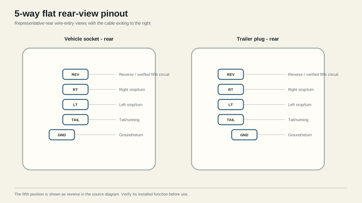
The base circuits are easier to verify when treated as commanded functions rather than colors:
| Circuit | Command used at the vehicle | Expected trailer response |
|---|---|---|
| Ground/return | Reference for every powered test | Stable return path for each operating load |
| Tail/running | Parking or head lamps on | Tail, marker, clearance, and applicable license illumination operate |
| Left stop/turn | Left indicator, then service brake | Left combined lamp follows both commands |
| Right stop/turn | Right indicator, then service brake | Right combined lamp follows both commands |
The left and right circuits are normally combined stop/turn feeds on this connector family. That does not mean one wire powers every brake lamp independently of the vehicle’s lighting architecture. A vehicle-specific converter or towing module may create the combined outputs. Diagnose a missing socket output on the vehicle side before changing the trailer.
Test the vehicle socket first
Disconnect the trailer and secure the vehicle. Establish the test reference using the equipment and vehicle instructions. Command running lamps, left turn, right turn, and service brakes one at a time. Record which contact responds to each command and whether any unintended contact responds.
This disconnected test establishes a boundary. If the correct vehicle-socket output is absent, the fault remains on the tow-vehicle side: a fuse, module, harness, connection, configuration, or other vehicle-specific cause. If all commanded outputs are present, continue through the trailer plug, harness, loads, and return path.
An unloaded tester can establish identity, but it cannot prove a corroded connection will support the operating load. If the correct signal is present unloaded and the lamp fails when connected, inspect the mating contacts and repeat measurements while the affected load operates. Check feed and return paths rather than assuming the lamp is defective.
Identify and test the fifth circuit
CURT identifies the fifth position on its 5-way flat reference as reverse. Lippert likewise describes the fifth conductor as a reverse function in its connector overview. A frequent application is a reverse-lockout solenoid on a hydraulic surge-brake coupler: reverse command reaches the fifth circuit, and the product uses that input according to its design.
The connector reference does not determine the following:
- whether this trailer actually has a lockout solenoid;
- whether the fifth position has been assigned to another function;
- the solenoid’s operating current or polarity requirements;
- acceptable conductor size or voltage drop for the installed length and load;
- required fuse or protection type and location;
- whether the tow vehicle supplies a suitable reverse output;
- the coupler’s manual bypass, service, or test procedure.
Those values belong to the exact coupler, actuator, solenoid, adapter, vehicle, and harness instructions. Generic pages sometimes publish a single wire gauge, fuse value, or voltage threshold as if it applied to every installation. This guide intentionally does not inherit those claims.
A bounded fifth-circuit test
- Inspect the coupler and identify the installed brake and lockout equipment by model where possible.
- Trace the fifth conductor from the trailer plug to its actual destination. Do not infer the destination from blue insulation alone.
- With the trailer disconnected and the vehicle secured under the vehicle procedure, command reverse and identify the vehicle-socket contact that changes state.
- Compare that result with the connector’s molded labels and the exact adapter or harness instructions.
- Connect only after the source and destination assignments agree.
- Perform the product-specified functional test in a controlled location, then repeat all lighting checks.
Record the connector half, view, contact, command, measured result, destination, and controlling document. That record lets a later repair distinguish an intentional fifth-circuit assignment from an accidental splice.
What a color can and cannot tell you
Blue is a useful clue because manufacturer diagrams often use it for the fifth reverse/auxiliary path on a 5-way flat. It is not a measurement. The same color is commonly associated with electric-brake output in other connector contexts. A previous owner may also have replaced a cord without preserving any convention. Function, terminal marking, and product documentation outrank insulation color.
Check surge-brake and adapter compatibility
Physical connection and electrical capability are separate decisions. A 7-way-to-5-way adapter may route a verified reverse circuit to the fifth flat position. A passive adapter cannot make a missing vehicle reverse signal appear. Likewise, a 4-way source contains only the four base circuits; changing its housing to five positions does not create the additional circuit.
Use this acceptance checklist:
| Check | Pass evidence | Stop condition |
|---|---|---|
| Connector identity | Five-way flat body and correct half confirmed | Body or view remains uncertain |
| Base lighting | Four commanded functions map correctly | Missing, crossed, or unintended output |
| Fifth source | Verified vehicle command reaches intended position | No output or a different command appears |
| Fifth destination | Conductor traces to documented equipment | Destination is unknown or improvised |
| Product limits | Exact instructions control wiring and test | Protection, load, or procedure is unknown |
| Connected operation | All required functions pass under operating conditions | Lockout, lighting, or return path behaves incorrectly |
Do not tow to diagnose an uncertain lockout circuit in normal traffic. Use a controlled product-approved test, keep clear of moving coupler parts, and stop when the brake equipment cannot be identified. A functioning reverse lamp at the vehicle does not by itself prove the trailer solenoid, wiring, ground, or hydraulic mechanism works.
If the trailer requires electric service-brake output or multiple independent auxiliary functions, a 5-way may not provide the required circuit capacity. Start with the connector types guide and count required functions. If the vehicle and trailer use different seven-contact families, identify them through the RV blade versus round-pin comparison before selecting an adapter.
Diagnose the result without changing several things
When a connected trailer has working lights but the lockout does not operate, preserve the successful lighting evidence. Recheck only the fifth path: vehicle reverse command, adapter output, mating contact, trailer conductor, solenoid connection, and return required by the product. When reverse operation works but a lamp fails, keep the fifth circuit unchanged and diagnose the affected base circuit.
If shifting to reverse causes an unintended lamp or another function, disconnect and compare both halves from their rear views. That symptom suggests a crossed assignment, but it does not identify which half is wrong. Test the vehicle socket independently, then trace the trailer plug. If the correct signal exists at both disconnected endpoints yet fails when mated, inspect fit, contact retention, contamination, and loaded voltage loss.
Use one repair cycle at a time:
- Record the symptom and current mapping.
- Isolate vehicle or trailer side while disconnected.
- Repair one verified fault.
- Repeat all five function checks, not only the original symptom.
- Update the handoff record.
This avoids a common failure pattern where a successful trial swap hides an orientation error while moving another circuit onto the wrong contact.
Close the job with five named results rather than “all lights work.” Record ground stability, tail/running, left stop/turn, right stop/turn, and the fifth function separately. Note whether each result was observed at the disconnected socket, at the trailer load, or both. Add the adapter part number and the exact product procedure used for the lockout. This detail matters when another vehicle connects later: identical housings do not prove the same reverse output, adapter routing, or protection. Reopen the record after any connector, cord, coupler, solenoid, or vehicle-harness change.
Sources
Last verified: August 25, 2026.