
A “6-pin trailer plug” is not one universal interface. CURT documents both 6-way round and 6-way square connectors. Six-way round systems also have a known brake-versus-auxiliary variation: Hopkins sells an adapter whose center contact can be switched to match trailers wired with center-pin electric brake or center-pin auxiliary. Identify the body, connector half, view, and installed assignment before applying power.
This is a high-risk reference because an incorrect assignment can energize trailer brakes from an auxiliary feed or place auxiliary power on the brake path. It does not specify wire size, circuit protection, brake capacity, or charging limits. Those decisions require the exact vehicle, connector, brake-controller, trailer, and load documentation.
Identify round or square form factor
Begin with the housing, not the wire colors. A 6-way round uses a circular keyed body with round contacts. A 6-way square uses a rectangular or square keyed body. They may carry similar categories of functions, but their physical layouts are not interchangeable.
Document these observations before opening a pinout:
- a photo or written description of the connector body and key;
- whether the part is mounted on the vehicle or attached to the trailer cable;
- whether you are looking into the mating face or at the rear terminals;
- molded terminal letters or function labels;
- the destination of the brake and auxiliary conductors;
- any adapter or previous repair between the vehicle and trailer.
A connector that has been modified, corroded, or assembled from an unidentified cord may not follow a familiar color convention. Do not call a position “brake” merely because a blue conductor reaches it. Hopkins explicitly instructs users to locate vehicle wires by function because color coding is not standard across all manufacturers.
Count functions as well as contacts
The four base paths are ground/return, tail/running, left stop/turn, and right stop/turn. A six-way commonly adds electric-brake and auxiliary-power paths. Contact capacity does not prove that both are present, correctly protected, or active at the tow vehicle. It also does not prove which one occupies the center on a round connector.
If the trailer has no identified electric service brakes but one contact is labeled for brakes, determine whether the connector is a replacement or whether equipment is missing. If the trailer has brakes, trace the brake conductor toward the brake junction and magnets rather than relying on the plug alone.
Orient the connector face
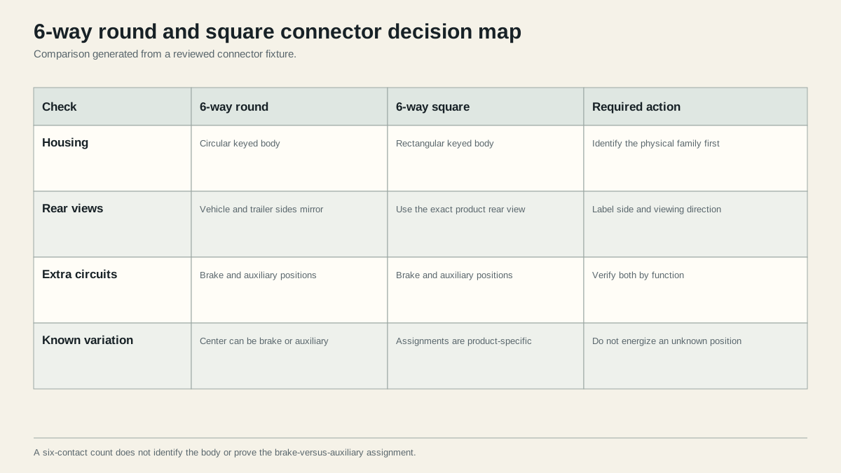
CURT’s guide describes its connector illustrations as representative rear views. A rear wire-entry view reverses left and right relative to the mating face. The vehicle socket and trailer plug are also opposite halves. A diagram copied without its caption can therefore create two layers of ambiguity.
Use the four-view orientation guide before translating positions if you cannot name the face. Keep the housing key in the same direction shown by the source. Prefer molded labels and the exact connector instruction sheet over a generic clock position.
A safe orientation record
Write a one-line header before recording circuits: “6-way round, vehicle socket, rear wire-entry view, key at top,” or the equivalent for the installed part. Sketch the key and label the center. Then enter measured functions. This prevents a later technician from reading the table from the opposite side.
For a square body, do not transfer the round layout. Use the terminal labels or instructions for that square connector. The same categories of circuit may exist while the contact geometry differs.
Verify brake and auxiliary assignments
Hopkins document 47570 is direct evidence that two six-pole round arrangements exist in actual adapter use. Its Quick-Change plug is designed for trailers with either center-pin electric brake or center-pin auxiliary wiring. That evidence is more reliable than a page declaring one center assignment exclusive.
Use this evidence order:
- Exact connector, adapter, trailer, and brake-controller instructions.
- Molded terminal markings on the installed part.
- A conductor traced to its actual destination.
- A controlled functional measurement following equipment instructions.
- General color conventions only as a clue.
Do not discover the assignment by connecting an unknown trailer and driving normally. Hopkins’ product has a specific switching and verification procedure for that adapter; it should not be generalized to other products. For an unidentified connector, disconnect power, inspect and trace the circuits, then follow the installed equipment’s test method.
Keep service brake and auxiliary evidence separate
For the brake path, identify the tow-vehicle controller output, connector contact, trailer brake junction, parallel magnet branches, and return path. For the auxiliary path, identify the source state, protection, intended load, and destination. A live auxiliary terminal is not proof that it is suitable for charging a particular battery.
Record “unknown” instead of forcing a choice when either path cannot be traced. An unknown brake/auxiliary pair is a stop condition because the possible failure is not limited to a lamp that stays dark.
Test compatibility before applying power
Compatibility has three layers:
| Layer | Pass condition | Failure example |
|---|---|---|
| Mechanical | Correct family mates fully and is retained | Round and square bodies or damaged keys do not match |
| Electrical identity | Every required contact has the intended function | Center brake and auxiliary assignments are reversed |
| Operating performance | Required loads work under documented conditions | Brake output, ground, or auxiliary path fails under load |
With the trailer disconnected, test the vehicle-side lighting functions one command at a time. Follow the brake-controller manual for its output test; controllers may not behave like a simple constant-voltage lighting circuit. Verify the auxiliary source and protection through vehicle-specific documentation. On the trailer, trace corresponding conductors and check the return path.
After identity checks pass, connect the secured trailer and repeat all required functions in a controlled setting. Stop if brakes apply unexpectedly, fail to apply under the specified test, an auxiliary contact powers the brake path, a connector heats, a ground is unstable, or any assignment conflicts with documentation.
Use the pinout lookup only after selecting the body and supported view. The lookup deliberately refuses unsupported or ambiguous selections. For normal electric-brake topology, continue to the electric trailer brake wiring reference.
Interpret adapter behavior without guessing
An adapter is evidence only for the product mapping printed in its instructions. A switchable Hopkins adapter acknowledges the center brake/auxiliary variation and provides a product-specific way to select between its two states. A fixed adapter may support only one state. Neither design proves how an unidentified trailer was wired.
Before buying or using an adapter, record the connector on each end, the center assignment on the six-way side, the source of brake output, the source and protection of auxiliary power, and every required lighting function. Compare that record with the adapter instruction sheet. Product marketing that says “7-to-6” confirms contact counts and intended interfaces; it does not by itself confirm the center assignment.
If a selectable adapter state produces unexpected brake application, stop and follow that adapter’s instructions. Do not use normal road towing as the diagnostic method and do not generalize one manufacturer’s switching procedure to a hard-wired connector. Once the correct state is established, label the vehicle, adapter, and trailer as one tested pairing and recheck it whenever a component changes.
For a permanent rewire, preserve the old mapping before removing terminals. A photo, terminal sketch, traced-function table, and part numbers make the change reversible and allow an independent reviewer to verify that brake and auxiliary paths were not transposed.
An unloaded continuity or voltage check is only an identity step. A loose terminal, corroded contact, weak return, or damaged conductor may show the expected state while no meaningful load is connected. After assignments are proven, repeat the product-specified checks under operating conditions and observe the connector for instability or heating. Do not invent a generic acceptable voltage drop or temperature threshold; use the limits and method supplied for the vehicle, controller, brake equipment, connector, and auxiliary load. If the result changes only under load, keep the verified position map and diagnose feed and return resistance rather than swapping brake and auxiliary contacts.
Sources
- CURT trailer wiring reference
- Hopkins 47570 Quick-Change product reference
- Lippert trailer wiring guide
- SAE J1239 scope
Last verified: August 25, 2026.