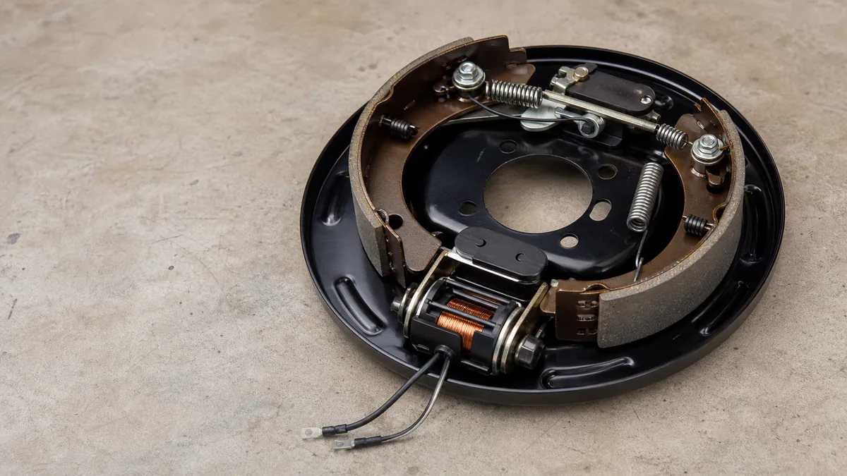
Do not start by turning down gain. First determine when the brakes apply, whether a valid brake command exists, and how many wheels are affected. All brakes locking only during a documented setup test can be a controller-setting problem. All brakes applying as soon as the connector is mated can indicate unintended electrical power or an active breakaway path. One wheel dragging with no electrical command points toward a local branch or mechanical assembly.
This page covers unexpected, excessive, or persistent application of electric trailer drum brakes. It does not cover weak or absent braking, normal gain setup on a healthy system, hydraulic surge-brake reverse lockout, or electric-over-hydraulic diagnosis. Identify the installed technology before using the decision path.
Out-of-service condition: Do not tow with uncontrolled, locked, dragging, unequal, overheated, or intermittently applying brakes. Secure the trailer against movement. Follow the vehicle, controller, trailer, axle, brake, and breakaway instructions. Do not lift or work beneath a trailer without its specified support points, rated equipment, and safe procedure.
Classify when and how many brakes lock
Record the symptom before disconnecting, moving, or adjusting anything. A useful record names the command state, event timing, affected wheels, connector state, controller display, trailer load, brake temperature, and any recent change.
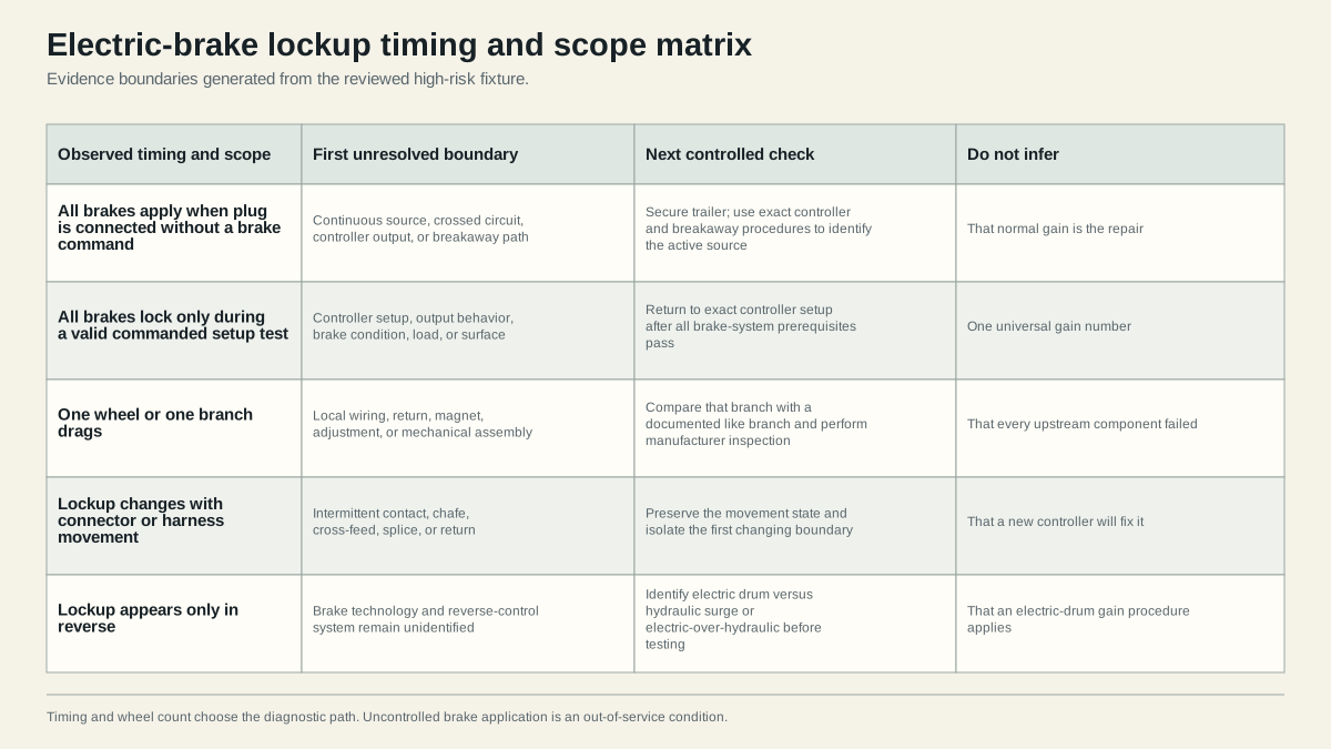
Build a timing and scope record
| Observation | First unresolved boundary | Keep separate from |
|---|---|---|
| All brakes apply when the plug is connected and no brake command is present | Controller output, crossed connector circuit, constant auxiliary feed, or breakaway source | Normal gain setup |
| All brakes lock during pedal or manual-control application | Controller setup, output behavior, brake condition, load, tire grip, or test surface | A no-command electrical fault until evidence supports it |
| Brakes pulse or apply when another electrical function operates | Connector assignment, cross-feed, ground/return, converter, or damaged wiring | Normal brake modulation |
| One wheel or one branch drags | Local conductor, splice, return, magnet, adjustment, bearing, or mechanical hardware | Replacing every controller or magnet |
| Brakes remain applied after command release | Continuing electrical output, breakaway path, switch state, or mechanical failure to release | A successful road test |
| Brakes lock only in reverse | Brake technology and reverse-control system | Assuming an electric-drum controller problem |
Record whether the symptom begins with the trailer stationary, connector insertion, ignition change, brake-pedal input, manual-controller input, another lamp or auxiliary command, forward motion, reverse motion, a turn, or harness movement. Also record whether it stops when the command is released. Do not repeatedly reproduce severe lockup merely to improve the description.
Identify the exact brake technology
A reverse-only complaint is a common place to mix systems. Hydraulic surge actuators can use a reverse lockout mechanism or solenoid. Electric drum brakes are commanded through a controller and brake circuit. Electric-over-hydraulic systems add an actuator with its own compatibility and diagnostic requirements. A seven-contact connector does not prove which system is present.
Capture controller, actuator, axle, brake assembly, breakaway kit, connector, and vehicle identities. If a label or manual cannot be found, stop and obtain product identification before testing. A procedure for a surge actuator can be irrelevant or unsafe on electric drum brakes, and a controller can explicitly exclude electric-over-hydraulic operation.
Distinguish lockup from drag and harshness
Use observable language:
- Lockup: one or more tires stop rotating under a braking event.
- Drag: a brake remains partially applied or resists rotation when release is expected.
- Harsh or grabbing application: braking begins abruptly but wheel rotation is not yet proven to stop.
- Unequal application: one wheel, side, or axle responds differently from documented comparable assemblies.
- Intermittent application: the state changes with vibration, connector movement, another circuit, temperature, or time.
These descriptions lead to different evidence. Dexter’s electric-brake troubleshooting material lists improper synchronization, controller faults, adjustment, broken or loose parts, contaminated components, faulty breakaway switches, and drum condition among possible causes across locking, harsh, surging, and dragging symptoms. The list supports multiple branches; it does not establish which cause is present on this trailer.
Check controller setup and continuous output
Separate two questions:
- Does the controller produce the documented response to a valid brake command?
- Does brake-circuit power remain or appear when the controller should not command it?
The first question belongs to setup and controller behavior. The second belongs to unintended application diagnosis. Do not combine them into one gain adjustment.
When lockup occurs only during valid commanded braking
Identify the controller model and every relevant control. Gain, output, sync, boost, aggressiveness, trailer profile, brake type, and integrated vehicle modes are not interchangeable names. Use the exact controller and vehicle manuals.
Tekonsha’s electronic brake-control instructions direct the operator to reduce output gain when the trailer brakes jerk or lock during the covered setup process. That instruction applies within its prerequisites and test sequence. It does not authorize gain adjustment as a repair for power present with no command, unequal wheel behavior, wiring damage, a pulled breakaway pin, or defective mechanical parts.
Before entering a normal setup loop, confirm:
- controller and brake technology are compatible;
- controller mounting, inputs, supply, ground, wiring, and configuration pass their procedures;
- connector assignments and return path are verified;
- brake branches and assemblies are serviceable and consistent;
- brake adjustment and applicable burnishing requirements are complete;
- tires, load, road surface, and test location meet the procedure;
- breakaway pin and system are in their normal ready state;
- no fault, overheating, drag, unequal response, or protection-device operation remains.
If those prerequisites pass, route to the brake-controller gain setup guide. If they do not, stay in diagnosis.
When brakes apply without a valid command
Use the exact controller procedure to observe its idle and commanded states. A controller display is useful evidence but is not a complete circuit test. Identify the vehicle brake-output terminal using the correct connector orientation, then follow the controller and vehicle instructions for checking whether unintended output exists.
Do not cut factory wiring, short terminals, bypass protection, or inject battery power based on a generic article. Vehicle tow modules and integrated controllers can require model-specific service information. Record the test method, electrical reference, connector state, load state, command state, and manual limit.
If a no-command output exists at the vehicle boundary, remain on the vehicle/controller path. If the vehicle boundary is correct but the state changes across the mated connector, inspect connector wiring, cross-feed, auxiliary power, trailer harness, breakaway circuit, and return. A familiar blue conductor is not proof of function.
When another function changes the brakes
Braking that changes with headlights, turn signals, reverse selection, plug movement, or auxiliary loads is strong evidence of a shared boundary or wrong assignment. Inspect both connector halves, rear wire-entry orientation, terminal retention, corrosion, water entry, heat damage, chafe, splices, junctions, and return paths.
Keep each observation separate. Headlights causing a brake symptom does not automatically prove a ground fault; it can also expose crossed circuits, a restricted return, damaged connector wiring, or product-specific module behavior. Locate the first boundary where the state changes under the same controlled command.
Inspect breakaway and brake wiring paths
The normal controller and breakaway battery can share the downstream trailer brake feed while using different sources. An active, damaged, miswired, or product-incompatible breakaway path can therefore apply multiple brakes independently of normal gain.
Inspect without improvising a breakaway test
Confirm the pin is fully seated in the correct switch and the cable, switch body, battery case, charger, and wiring are physically intact. Look for a pin partially withdrawn, damaged housing, trapped cable, corrosion, water, loose splices, heat, or a battery problem. Do not pull the pin merely to see what happens.
The correct connection state and pull-pin procedure depend on the breakaway kit and controller. Some products require the tow-vehicle electrical plug to be disconnected during testing. Use the breakaway functional-test guide only after identifying the exact kit and controller.
If brakes remain applied when the tow-vehicle plug is disconnected under a safe state permitted by the product instructions, the trailer-side stored-energy path or mechanical assemblies remain candidates. That observation does not by itself prove a defective switch; the exact battery, switch, feed, branches, return, and mechanical release still need isolation.
Trace by source and boundary
Use the electric trailer brake wiring diagram to understand the conceptual paths. Then verify the installed system:
- controller and vehicle brake-output boundary;
- vehicle socket and trailer plug function mapping;
- trailer junction where normal and breakaway paths join, if applicable;
- main brake feed and return;
- parallel axle or wheel branches;
- magnet leads and exact brake assemblies.
Preserve the first passing and first failing points. If all brakes apply together, inspect shared upstream sources and junctions before opening every wheel. If one branch differs, move toward that branch. If movement changes the symptom, hold the trailer stationary and isolate the changing connector, cable, splice, or chafe point without repeatedly energizing a damaging condition.
Do not diagnose by voltage presence alone
A no-load meter reading can exist through a restricted path, and a transient or pulse can be interpreted differently by different meters. Conversely, electronic controllers may use monitoring behavior that is not a service-brake command. Use the controller, vehicle, and brake manufacturer’s specified test, instrument, load state, and pass limits.
Never apply a universal resistance, current, voltage, wire size, fuse, or breaker value to an unidentified brake population. Record the exact number of brakes and their manufacturer/model before comparing product tables.
Separate electrical lockup from mechanical drag
Electrical application should change with the controlling source. Mechanical drag can remain after electrical sources are in their documented released state. The handoff occurs only after the controller, connector, breakaway path, feed, branches, and return have been tested under the applicable procedures.
Compare wheels only when safely supported
If the brake manufacturer procedure requires wheel rotation or inspection, use the trailer manufacturer’s lift points and rated stands on a stable surface. Chock as directed, keep people clear, and never support the trailer on an axle or suspension point when the instructions prohibit it. Do not crawl beneath an inadequately supported trailer.
With electrical sources confirmed in their released states, compare documented like wheels. One wheel that remains resistant can point toward over-adjustment, contaminated or damaged parts, a seized lever, broken hardware, drum condition, bearing condition, or another local mechanical cause. All wheels dragging can still reflect shared setup, incorrect adjustment across assemblies, an active electrical source, or a procedure issue.
Brake dust can be hazardous. Dexter warns against creating or breathing dust and against compressed-air or dry-brush cleaning for covered brake service. Opening an assembly requires the exact manual, protective method, tools, and competence.
Preserve heat and release evidence
Do not touch a wheel, hub, drum, magnet area, connector, or conductor after a lockup event. Components can remain hot enough to burn, and a dragged bearing or tire problem can create heat unrelated to electrical brake command. Move people away, watch for smoke or fire risk, and follow the vehicle and trailer emergency procedure.
When the manufacturers permit inspection after safe cooling, record which wheel or electrical boundary showed discoloration, odor, melted material, damaged grease seals, or other distress. A suitable non-contact comparison method can help identify a different wheel, but there is no universal article-level temperature threshold. Ambient temperature, braking history, bearing condition, axle load, brake design, measurement location, distance, and instrument accuracy affect the reading.
Treat heat as localization evidence, not proof of one failed part:
- one unusually hot wheel keeps its local brake, bearing, tire, and branch in scope;
- several similar hot brakes keep shared command, setup, load, and test history in scope;
- a hot connector or splice keeps resistance, contact, conductor, and load problems in scope;
- no obvious heat does not clear an intermittent application that stopped before inspection.
Photograph and record the state before disassembly when safe. Do not cool a hot brake with water or resume towing because it releases after cooling. A heat-damaged component requires the applicable inspection and replacement decision.
Use a pass/stop record
| Final evidence | Decision |
|---|---|
| No-command electrical state passes, every brake releases, mechanical inspection passes, and documented setup produces coordinated braking | Record conditions and complete the full post-service verification |
| Lockup occurs only during a valid setup test and disappears through the controller’s bounded documented adjustment | Confirm the result across every required test and retain the setting with its conditions |
| Any brake remains powered without command | Out of service; isolate controller, connector, cross-feed, or breakaway source |
| One wheel remains mechanically resistant after electrical release is proven | Out of service; inspect that assembly and related running gear |
| Results are unequal, intermittent, contradictory, or outside product limits | Out of service; obtain qualified diagnosis |
After repair, reproduce the same controlled states that originally caused the symptom. Verify no-command release, pedal and manual-control behavior where applicable, every brake branch, normal controller setup, breakaway readiness, connector stability, and absence of heat or protection-device operation.
Do not perform an uncontrolled public-road test to find out whether lockup returns. Use only the safe location, load, surface, speed, and sequence specified by the installed controller, vehicle, trailer, and brake instructions after stationary checks pass.
The trailer brakes not working guide owns weak or absent braking. If a repair changes the symptom from lockup to weak braking, start a new evidence record rather than continuing to adjust gain.
Sources
- Dexter electric-brake service and troubleshooting manual
- Tekonsha electronic brake-control instructions
- etrailer trailer-brake troubleshooting guide
Last verified: August 26, 2026.