
A trailer connector diagram needs four coordinates: connector family, vehicle or trailer half, mating or wire-entry face, and key orientation. If any coordinate is missing, left and right may appear reversed. Do not move conductors until the drawing and the installed connector are held in the same view.
This page uses a 7-way RV blade as the visual example because its asymmetric key and multiple contacts make the transform easy to see. The method applies to other paired connectors, but the circuit positions do not transfer from one family to another.
Name the four possible diagram viewpoints
The two physical halves are normally:
- Vehicle socket: the receptacle mounted on or connected to the tow vehicle.
- Trailer plug: the cable-end connector attached to the trailer.
Each half can be drawn from either side:
- Mating face: the contact surface that faces the other connector when joined.
- Rear or wire-entry face: the terminal side where conductors enter the housing.
That creates four labels: vehicle mating face, vehicle rear, trailer mating face, and trailer rear. “Front,” “back,” “male,” “female,” “car end,” and “plug side” may be useful conversational clues, but they are not precise enough on their own.
Add the family and key orientation:
7-way RV blade, vehicle socket, rear wire-entry view, key at top.
Now the drawing has a stable coordinate system. For a 5-way flat, the stabilizing feature might be the cable exit and exposed ground contact. For a 6-way round, it might be the housing key and center terminal. Do not rotate the connector after recording the orientation.
Why official diagrams can look different
CURT’s guide explicitly describes its illustrations as representative rear views and labels vehicle side and trailer side. A different manufacturer may show the mating face. Both can be correct. The conflict appears only when a view caption is missing, cropped, or ignored.
Wire colors create a second source of apparent conflict. CURT warns that illustrated colors may not represent the installed colors. An orientation mismatch and a color-convention mismatch can occur at the same time, so function testing must remain independent of both.
See how mating faces mirror each other
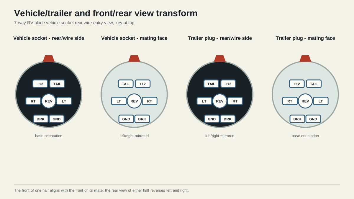
Think of a transparent connector held with the key fixed at the top. When you walk from the rear to the mating face, the left contact appears on the right. The same reversal occurs between the rear views of the vehicle and trailer halves because their mating faces oppose each other.
For the fixture shown:
| View | Relationship to vehicle rear base |
|---|---|
| Vehicle rear/wire side | Base orientation |
| Vehicle mating face | Left/right mirrored |
| Trailer rear/wire side | Left/right mirrored |
| Trailer mating face | Base orientation |
The center stays in the center. Top and bottom stay top and bottom when the key remains fixed. Left-side and right-side positions exchange. If a connector is physically rotated, that rotation must be recorded separately; do not silently compensate while reading the table.
Mating is not the same as matching labels on paper
When connected, corresponding vehicle and trailer contacts physically touch. Rear-view drawings must therefore look mirrored for the contacts to meet. Placing two identical rear drawings side by side may look neat but can be wrong unless one half has already been transformed.
This is why deterministic generation matters. The fixture stores one contact set and explicit mirrorX state for each view. Labels, positions, and explanatory text can be checked against the same data rather than redrawn by hand.
Translate a circuit between views
Use this method only after identifying the connector family.
- Write the full source-view label and installed-view label.
- Put the key or other asymmetric feature in the same orientation for both.
- Mark one anchor contact, such as center, molded ground, or another documented terminal.
- Decide whether the change crosses from rear to mating face or between opposing rear views.
- If it does, mirror left and right once. Do not also rotate the drawing.
- Transfer the function label, not the conductor color.
- Independently verify the installed circuit before energizing a load.
Example: a function shown at the upper-left of the vehicle rear appears upper-right on the vehicle mating face and upper-right on the trailer rear. It returns to upper-left on the trailer mating face. This describes geometry only. The exact function still comes from the correct RV-blade fixture or product diagram.
Use a translation worksheet
| Field | Record |
|---|---|
| Connector family | Exact physical family and part number if available |
| Source diagram | Vehicle/trailer, mating/rear, key direction |
| Installed view | Vehicle/trailer, mating/rear, key direction |
| Anchor contact | Molded label or documented position |
| Transform | None, mirror left/right, or unresolved |
| Function evidence | Measurement, trace, terminal label, exact manual |
| Result | Pass, conflict, or stop |
If the transform requires both a mirror and an uncertain rotation, stop and obtain a better diagram or expose the rear labels safely. A worksheet with “unresolved” is safer than a confident-looking color map built from two assumptions.
Recover from three common view conflicts
The colors match but positions do not. Keep the key fixed and determine whether one drawing is a mating face while the other is a rear view. Ignore color temporarily and compare one documented function. If positions align after one mirror, record the corrected view labels. If they do not, investigate another connector family or wiring convention.
Vehicle and trailer diagrams look identical from the rear. Corresponding rear views normally need a left/right relationship that lets mating contacts meet. Confirm whether one illustration was already mirrored for convenience or whether its caption actually says front view. Do not mirror it a second time.
The installed connector has no obvious top. Look for the locking lid, key, notch, flat, molded index, fastener pattern, or terminal lettering defined by the product. If no feature establishes orientation, use the exact part drawing. An arbitrary “top” chosen from how a loose plug lies on a bench is not stable evidence.
Take before-and-after photos from the named view. Include the key and rear labels. A later reviewer should be able to place the connector in the same orientation without relying on memory.
When no translation is appropriate
Do not translate between different physical families. Do not move an RV-blade map into a seven-round-pin connector, a six-round map into a six-square body, or a North American reference into an imported interface based only on contact count. Geometry can mirror one known family; it cannot reconcile different standards.
Also avoid translation when an adapter contains internal electronics, switching, or product-specific routing. Treat the adapter input and output as two documented interfaces and test its mapping under the manufacturer instructions.
Perform a one-contact sanity check
Before translating the entire connector, choose one low-ambiguity documented contact and test the geometry. Center is useful when the family has a true center, but it cannot prove left/right orientation. A molded ground or keyed adjacent terminal can provide the second anchor. Confirm where both anchors appear in the source and installed views.
If center agrees and the second anchor appears on the opposite side, one left/right mirror is likely required. If both anchors disagree, the problem may be rotation, the wrong connector half, a different family, or an inaccurate source. Stop rather than applying another transformation until the discrepancy is identified.
After the sanity check, transfer the remaining labels as one set. Do not flip individual circuits selectively to match colors. Verify the finished set with commanded functions and exact equipment documentation.
Write the connector half, viewing face, and key position beside every saved sketch or photograph; an unlabeled image can recreate the same ambiguity during the next repair.
Verify molded labels before moving wires
Geometry can translate a known map, but it cannot prove the installed connector follows that map. Use this evidence order:
- Measured or traced circuit function under the appropriate test procedure.
- Molded terminal function marking on the exact connector.
- Instructions for the exact connector, vehicle, trailer, controller, or adapter.
- A general orientation-specific reference for the identified family.
- Wire color only as a clue.
With the trailer disconnected and vehicle secured, command lighting outputs one at a time. Follow the brake-controller instructions for brake output; do not treat it as an ordinary lamp feed. Verify auxiliary power, protection, and intended load through vehicle-specific documentation. Then trace the trailer side to each load and return.
Use the 4-way flat reference or 7-way RV blade reference only after the family is confirmed. The pinout lookup offers only views supported by its reviewed fixture and routes to the full canonical page.
Stop when the family, half, face, key, molded labels, or circuit behavior conflicts. Also stop for heat damage, arcing, displaced contacts, unstable ground, unexpected brake application, or undocumented auxiliary power. A mirrored diagram is a coordinate problem; it should never be solved by trial-and-error energizing.
After a repair, repeat the full required function set from both the disconnected vehicle socket and the connected trailer. A corrected left/right map does not validate brake output, auxiliary power, connector retention, or loaded ground performance. Close the housing only after terminal placement, strain relief, sealing, and the product-specific inspection all pass.
Sources
Last verified: August 25, 2026.